
User's Manual


Installing the Ethernet Cable 3G Alarm Communicator Installlation Manual
6
person or other persons). The Communicator shall be installed and used within an environment that provides the pollution degree max 2, overvoltages category II, in
non-hazardous, indoor locations only. This manual shall be used with the Installation Manual of the panel which is connected to the 3G/GPRS/Ethernet Communica-
tor. All instructions specified within the panel manual must be observed.
All the local rules imposed by local electrical codes shall be observed and respected during installation.
Installing the Ethernet Cable
(TL260R/TL2603GR only)
A Category 5 (CAT 5) ethernet cable must be run from a source with Ethernet/Internet connectivity to the Communicator module, inside the Panel. The Com-
municator end of the cable must be terminated with an RJ45 plug, which will connect to the Communicator’s RJ45 jack after the Communicator is installed. All
requirements for installation of CAT5 ethernet cable must be observed for correct operation of the Communicator, including, but not limited to, the following:
• Do NOT strip off cable sheathing more than required for proper termination.
• Do NOT kink/knot cable.
• Do NOT crush cable with cable ties.
• Do NOT untwist CAT5 pairs more than ½ in. (1.2cm).
• Do NOT splice cable.
• Do NOT bend cable at right angles or make any other sharp bends.
NOTE: CAT5 specification requires that any cable bend must have a minimum 2 in. (5 cm) bend radius. Maximum length of CAT 5 cable is 328 ft.
(100 m).
Running the RS-422 Cable
An RS-422 cable must be connected to the C24-HUB and cable run to the Communicator module inside the panel.
NOTE: Maximum cable length for RS-422 cable is 1,000 ft. (305 m).
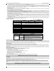
At the C24-HUB, make connections as follows:
1. Securely fasten the TX+ wire on the terminal block.
2. Securely fasten the TX- wire on the terminal block.
3. Install a 120
¼ W resistor between the RX + and RX- terminals at the C24-HUB.
4. Securely fasten the RX+ wire on the terminal block.
5. Securely fasten the RX- wire on the terminal block.
6. (Optional) Securely fasten the GND wire on the terminal block.
NOTE: The GND connection is optional. DSC recommends connecting the GND wire at both ends.
7. Run the RS-422 Cable from the
C24-HUB
to the inside of the Panel.
Inserting and Removing the SIM Card
1. Remove the front cover of the Panel to access SIM holder.
2. Remove power from the panel and disconnect the battery and telephone line.
3. On the SIM card holder push gently to slide the cover towards the Printed Circuit Board (PCB) antenna, as indicated by the arrow on SIM holder, to OPEN.
This will unlatch the SIM card holder on the side closest to edge of the Communicator PCB. (See Figure 3).
4. Lift up the SIM card holder from the side that is not hinged.
NOTE: The SIM can be damaged by bending, or scratching contacts. Use caution when handling SIM cards.
5. Insert or remove the SIM card, noting the orientation of the notches on the SIM card and the SIM card holder.
6. When inserting a SIM card, insert the card in the proper orientation and gently push the SIM card holder down and slide the holder as indicated by the arrow
on SIM holder, to LOCK.
7. Reconnect the backup battery and telephone line, apply AC power to panel, and replace the panel cover.
Hardware Reset
The Communicator can be hardware reset by installing a jumper between Pins 4 and 5 on the AUDIO/DEFAULT connector and restarting the Communicator.
Installing jumper during normal operation has no effect.
Installing Communicator with PC1616/1832/1864 Panel
NOTE: Before installing Communicator or inserting/removing SIM, ensure that system power is OFF and telephone line is disconnected.
1. To assemble supplied mounting bracket, perform the following: (See Figure 1).
a. Remove the 4 white plastic standoffs from the bag provided with the Communi-
cator kit.
b. Insert the 4 standoffs through the back of the mounting bracket, into the holes at
each corner. (The antenna mounting tab should be facing away from you).
c. Place the bracket on a flat, solid surface. Hold the Communicator component
side up and orient the 4 holes on the Communicator with the 4 standoffs pro-
truding from the bracket. Push the Communicator firmly and evenly onto the
standoffs until it is securely attached to the mounting bracket.
d. Remove the panel front cover.
e.
TL260R/TL2603GR only
: Remove and discard the circular knockout located in
the top-right section of the panel. (This hole will be used for connection of the sup-
plied radio antenna).
f. TL260R/TL2603GR only: Connect the supplied 5” (12.7 cm) antenna cable to
the radio, by passing the connector through the hole on back of the mounting
bracket to the Communicator board. Push the antenna connector firmly into
the socket on the 3G/GPRS radio. (See Figure 3).
2. Install the Communicator into the panel:
a. Attach one end of the PC-LINK cable to the panel PC-LINK header on the
panel (red wire goes on Pin 1 of the panel PC-LINK header).
b. Insert the assembled Communicator into the panel.
NOTE: Ensure that the threaded antenna connection point is visible through
the knockout hole at the top right of the panel.
c. TL260R/TL2603GR only: Place the nylon washer with bushing (thick flat washer) onto the threaded section of the antenna cable. Insert the threaded
section through the antenna mounting knockout hole at top right of panel.
d. Place the second nylon washer (flat), followed by the brass washer and the brass nut, onto the threaded section of the cable, outside the panel. Tighten
the assembly by hand only. (Finger tight only- Do not overtighten the antenna assembly).
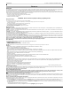
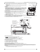
INSTALLING THE 3G/GSM/ETHERNET COMMUNICATOR IN PANEL
DG0009744
Brass Washer
Nylon washer (flat)
Nylon Washer
with bushing
(thicker flat washer)
Brass nut
Antenna
Mounting Tab
Mounting
Holes
Mounting Holes
Antenna
Cable
Mounting Plate
for UA601
External Antenna
Screw Thread
Communicator
Board
Mounting
Plate
Stand Off
Figure 1 Communicator
Mounting Bracket