
User's Manual


Network Activity LEDs (Red and Green) 3G Alarm Communicator Installlation Manual
10
NOTE: The Communicator will indicate 3G/GSM Trouble (yellow LED = 5 flashes) if the calculated average CSQ Level is 5 or less. The Communicator Signal
Strength can be viewed remotely with Connect24.
Network Activity LEDs (Red and Green)
(TL2603GR only)
• Ethernet Activity: Red LED will blink quickly once for Ethernet Transmit, or twice for Ethernet Receive.
• 3G/GPRS Activity: Green LED 2 will blink quickly once for 3G/GPRS Transmit, or twice for 3G/GPRS Receive.
Network Link LED (Yellow)
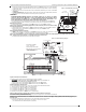
(TL260R only) See Figure 3 for location of LED.
The TL260R uses an additional Link LED on the board. LED is lit to indicate an active Ethernet connection.
.
Factory Defaults Reset
You can reset the programming options for the Communicator to the factory settings by installing the hardware jumper. Perform the following steps to reset the
Communicator:
NOTE: A jumper is required on AUDIO/DEFAULT pins 4 and 5 to reset the hardware values.
1. Remove Panel front cover.
2. Locate the AUDIO/DEFAULT 5 pin connector on the Communicator board. (See Figure 3).
3. Apply a jumper to short the hardware default pins 4 and 5.
4. Remove AC and DC power from the panel and then reapply power to the Panel. Wait until the two green LEDs on the Communicator begin flashing rapidly.
5. Remove the jumper from the hardware default pins 4 and 5. (Green LEDs will stop flashing).
6. Replace the Panel cover.
NOTE: Your Communicator has now been reset to the factory default values.
Firmware Update
The firmware of the device can be updated over 3G/GPRS or Ethernet (Remote or Local updating):
• When the firmware update begins, all 4 LEDs are ON.
• During the firmware update process, the LEDs will be cycled individually in a chaser pattern.
• After a successful update, the unit will automatically restart.
• Should the update fail, all 4 LEDs will flash ON, then OFF together at 1 second intervals.
NOTE: If the firmware update fails, restart the Communicator by cycling Power. For persistent update failures, contact your dealer. For UL/ULC listed installa-
tions, only local firmware updates are allowed.
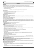
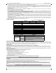
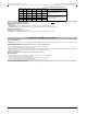
1 Bar 1 - 4 ON OFF Flashing -108 ~ -103
Relocate Panel or install external antenna
if Yellow Trouble LED has:
5 flashes.
2 Bars 5 - 6
OFF
See Note
OFF Flashing -102 ~ -99
3 Bars 7 - 10 OFF OFF ON -98 ~ -91
Location is OK
. 3G/GPRS Signal Strength
is greater than CSQ 5.
4 Bars 11-13 OFF Flashing ON -90 ~ -85
5 Bars 14 + OFF ON ON
-84 and
higher
COMMUNICATOR RESET / UPDATE
Table 4: Radio Signal Strength (Continued)
Signal
Strength
CSQ
Level
Yellow
LED
Green
Led 2
Green
LED 1
Signal Level
dBm
Action Required