3G2060(R) HSPA/3G WIRELESS ALARM COMMUNICATOR 3G Communicator – North America TL260(R) ETHERNET/INTERNET ALARM COMMUNICATOR Ethernet Communicator TL2603G(R) ETHERNET/INTERNET AND HSPA/3G DUAL-PATH ALARM COMMUNICATOR 3G / Ethernet Communicator - North America Installation Manual v3.0 Warning: This manual contains information on limitations regarding product use and function and information on the limitations as to liability of the manufacturer.
3G Alarm Communicator Installlation Manual TABLE OF CONTENTS Warning: Installer Please Read Carefully . . . . . . . . . . . . . . . . . . . . . . . . . . . . . . . . . . . . . . . . . . . . . . . . . . . . . . . . . . . . . . . . 3 Initial Panel Programming. . . . . . . . . . . . . . . . . . . . . . . . . . . . . . . . . . . . . . . . . . . . . . . . . . . . . . . . . . . . . . . . . . . . . . . . . 9 Communicator Technical Specifications . . . . . . . . . . . . . . . . . . . . . . . . . . . . . . . . . .
G Alarm Communicator Installlation Manual Warning: Installer Please Read Carefully WARNING: INSTALLER PLEASE READ CAREFULLY Note to Installers Motion Detectors The Warnings on this page contain vital information. As the only individual in contact with system users, it is the installer’s responsibility to bring each item in this Warning to the attention of all users of this system.
IMPORTANT 3G Alarm Communicator Installlation Manual GENERAL IMPORTANT This installation manual shall be used in conjunction with the Power Series Alarm Controller Power Panel manual. All the safety instructions specified within that manual shall be observed. (or equivalent). The Alarm Controller Power Panel is referenced as the “panel” throughout this document.
3G Alarm Communicator Installlation Manual • • • • • • Ratings Compatibility • P3 (3G/GSM and Ethernet in redundant configuration, Panel Section [851][005] Toggle Option [5] ON). The Communicator can also be used as an Active communication system with the Security Levels A1-A4 (each channel 3G/GPRS or Ethernet independent or together in a back-up/redundant configuration).
Installing the Ethernet Cable 3G Alarm Communicator Installlation Manual person or other persons). The Communicator shall be installed and used within an environment that provides the pollution degree max 2, overvoltages category II, in non-hazardous, indoor locations only. This manual shall be used with the Installation Manual of the panel which is connected to the 3G/GPRS/Ethernet Communicator. All instructions specified within the panel manual must be observed.
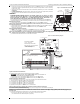
3G Alarm Communicator Installlation Manual Installing Communicator with PC1616/1832/1864 Panel e. Locate the screw hole on the right side wall of the panel. See Figure 2 (screw). Line up the assembled Communicator with the right side wall of the panel and, using the screw provided, secure the mounting bracket to the panel. f. Attach the other end of the PC-LINK cable to the Communicator (black wire goes on Pin 1 of the Communicator). g.
Keypad Data Display 3G Alarm Communicator Installlation Manual b. Observe that the Communicator’s red and yellow LEDs are flashing together while it initializes. The red and yellow LEDs will continue to flash until the Communicator has successfully communicated to all programmed receivers. If this is the first time the Communicator has been powered up in the panel, the module will initiate communication to Connect24 to request remote programming. NOTE: Initialization may take several minutes to complete.
3G Alarm Communicator Installlation Manual Yellow Trouble LED 5. Alternately, you can reposition the Panel to improve signal strength. Dismount the panel and move it to another location to achieve the required signal strength. If the Panel is relocated to improve signal strength, mount it in the new location. 6. When final Panel/antenna location is determined, continue at the Initial Panel Programmingsection. COMMUNICATOR STATUS LEDS The Communicator has 4 onboard LED indicators.
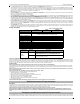
Network Activity LEDs (Red and Green) 3G Alarm Communicator Installlation Manual Table 4: Radio Signal Strength (Continued) Signal CSQ Strength Level Yellow LED Green Led 2 Green LED 1 1-4 ON OFF Flashing 2 Bars 5-6 OFF See Note OFF Flashing 3 Bars 7 - 10 OFF OFF ON -98 ~ -91 4 Bars 11-13 OFF Flashing ON -90 ~ -85 ON -84 and higher 1 Bar 5 Bars 14 + OFF ON Signal Level dBm Action Required -108 ~ -103 Relocate Panel or install external antenna if Yellow Trouble LED has: -1
3G Alarm Communicator Installlation Manual Firmware Update _____________________________________________________________________________________________________________________________________________________________________________________________________________________________________________________________ APPENDIX A: COMMUNICATOR TROUBLESHOOTING Table 5: Trouble LED indications Trouble indication Possible Causes No Indication No Power Yellow LED – ON Solid Insufficient Signal Strength Trouble
System Options 3G Alarm Communicator Installlation Manual ETHERNET/CELLULAR PROGRAMMING OPTIONS The Programming Sections described in this document can be viewed at the SCW LCD. To start programming enter: [*][8][installer code] [851][# # # ], Where # # # is the 3 digit Section number referenced in this section. The Programming Worksheets at the end of this document can be used to record the new values when programming changes have been made from the default values.
3G Alarm Communicator Installlation Manual System Options NOTE: Commercial supervision is more data intensive than residential supervision and should only be used when required to meet the approval for the installation. [4] Primary Path Default (OFF - TL2603GR/TL260R) (ON - 3G2060R) ON: Cellular channel is the primary path. Ethernet channel is the secondary path, if it exists. OFF: Ethernet channel is the primary path in a dual Communicator. Cellular channel is the secondary path.
Programming Options 3G Alarm Communicator Installlation Manual Enter the IP address for DNS Server 1. Format is 4 fields, each field is a 3 digit decimal. Valid range: 000-255. NOTE: If no value is programmed and DHCP is used, the DHCP Server will configure the address. If an address is programmed and DHCP is used, the address that you program will be used instead of the DHCP address. [008] DNS Server IP 2 Programming this Section is not permitted on a UL/ULC listed system. Default (000.000.000.
3G Alarm Communicator Installlation Manual System Test Options [026 - 029] [024] Panel Absent Trouble Restore Default (FF) Program 00 to disable this event or FF to enable. This event will occur when communications with the control panel have resumed. [025] Radio Activation Restore Default (FF) Program 00 to disable this event or FF to enable. This event will occur after any successful Connect24 programming session.
Ethernet Receiver 1 Options 3G Alarm Communicator Installlation Manual Table 7: Panel Tamper Alarm Restore Event SIA Identifier SIA Reporting Code Contact ID Qualifier Contact ID Event Code Contact ID Reporting Code Contact ID User/Zone [033]Comm. FW Update Begin LB 00 1 9 03 002 [034]Comm.
3G Alarm Communicator Installlation Manual Ethernet Options [112] Ethernet Receiver 2 DNIS Default (000000) The DNIS is used in addition to the account code to identify the Communicator module at the central station. Valid range: 000000 099999. Value is entered as leading 0 followed by the 5-digit DNIS. Format is BCD. NOTE: Each Ethernet/Cellular receiver must be programmed with a unique DNIS. [113] Ethernet Receiver 2 Address Default (000.000.000.
Cellular Receiver 2 Options 3G Alarm Communicator Installlation Manual [203] Cellular Receiver 1 Address Default (000.000.000.000) Enter the Cellular Receiver 1 IP address. This information will be provided by your central station system administrator. Each 3-digit segment of the address must be within a valid range of 000-255. NOTE: When a valid IP address has been entered, the Cellular is enabled and will communicate events over the Cellular channel.
3G Alarm Communicator Installlation Manual Command and Control Options [222] Cellular Login User Name Default ( ) Some network carriers require you to provide login credentials when connecting to an APN. Program your login User Name in this Section. Format is up to 32 ASCII characters. NOTE: This Section is not accessible via SCW keypad programming. [223] Cellular Login Password Default ( ) Some network carriers require you to provide login credentials when connecting to an APN.
SMS Command and Control Functions 3G Alarm Communicator Installlation Manual [311] - [318] SMS Phone Number 1 - 8 Default ( ); These Sections may be programmed through DLS IV or the keypad. Up to 8 SMS telephone numbers (4 - 32 digits) can be programmed in Section [31x] Where x is an SMS telephone number from 1 to 8. Leaving programming blank for a telephone number will disable that number. The User can program their own mobile telephone numbers at the keypad using [*] [6] <> “SMS Programming”.
3G Alarm Communicator Installlation Manual SMS Command and Control Response [616] Alarm Memory Request Default (Alarm Memory Request); Send this command to the system to request the alarm memory from the system. This command may be followed by a Partition Label or partition number, and Access Code. If partition label is omitted, alarm memory of all partitions will be sent. Alarm memory responses will include Partition label and Zone label. Up to 8 partitions may be contained in 1 message.
SMS Command and Control Response 3G Alarm Communicator Installlation Manual [634] Error Code Default (Error Code); When an SMS initiated function fails, the module will send an error code to the telephone number that was source of the SMS request. Message format is: [Account Label] [Date and Time] [Error Code] [Error Type]. Fields are “space” delimited.
3G Alarm Communicator Installlation Manual System Information (Read Only) RECEIVER DIAGNOSTIC TESTING [901] Diagnostic Test Transmission [1] Ethernet 1 (OFF). [2] Ethernet 2 (OFF). [3] Cellular 1 (OFF). [4] Cellular 2 (OFF). [5],[6],[7],[8] Reserved (OFF). This Section may be used by the installer to force the Communicator to send an immediate test transmission to specific receivers, to verify that the communications paths are available.
Communicator Status, Initialization, Diagnostics and Trou- 3G Alarm Communicator Installlation Manual COMMUNICATOR STATUS, INITIALIZATION, DIAGNOSTICS AND TROUBLESHOOTING [984] Communicator Status The communicator status sections are intended to provide the installer with real-time status of the communicator’s functionality, operational readiness, failures, and potential malfunctions that may affect flawless operation of the communicator and its primary function of sending signal to the central station in
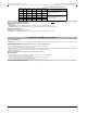
3G Alarm Communicator Installlation Manual Communicator Status, Initialization, Diagnostics and Troubleshooting Table 12: Radio Initialization Status - 1-8 bits completion Bit Not Completed Completed 1 1 2 2 3 3 4 4 5 5 6 6 7 7 8 8 For example, the radio initialization status code 12-45--- indicates that Radio has been powered up, it has received SMS signal from C24, the radio is attached to the network, and Receiver 1 has been initialized. This code could be followed with...
Communicator Status, Initialization, Diagnostics and Trou- 3G Alarm Communicator Installlation Manual Communicator Troubleshooting The status code for the radio signal strength, its typical troubles, possible causes and troubleshooting instructions is displayed in the table below. Table 14: Radio Signal Strength Signal Strength CSQ Level Signal Indicator 1 Signal Indicator 2 Signal Level Signal Level [dBm] Status No Signal 0 0 0 -108.
3G Alarm Communicator Installlation Manual Communicator Status, Initialization, Diagnostics and Troubleshooting Firmware Update Diagnostics Section The firmware updates can be made from communicator. Communicator can update firmware of the panel and also of communicator itself.
Communicator Status, Initialization, Diagnostics and Trou- 28 3G Alarm Communicator Installlation Manual
3G Alarm Communicator Installlation Manual System Options ETHERNET/CELLULAR PROGRAMMING WORKSHEETS SYSTEM OPTIONS [020] Time Zone [001] Ethernet IP Address Default (CAFE) Valid range: 0000 - FFFF. |____|____|____|____| Default (000.000.000.000) |____|____|____||____|____|____||____|____|____|____|____|____| [002] Ethernet IP Subnet Mask [022] Communications Format Default (04) Program 03 (CID), 04 (SIA). Default (255.255.255.
Ethernet Receiver 1 Options ETHERNET RECEIVER 1 OPTIONS [101] Ethernet Receiver 1 Account Code Default (0000000000) Valid range: 0000000001 - FFFFFFFFFE. 3G Alarm Communicator Installlation Manual [115] Ethernet Receiver 2 Local Port Default (0BF9/3065) Valid range: 0000 -FFFF. |____|____|____|____| |____|____|____|____|____|____|____|____|____|____| [116] Ethernet Receiver 2 Domain Name Default ( ) [102] Ethernet Receiver 1 DNIS Default (000000) Valid range: 000000 - FFFFFF.
3G Alarm Communicator Installlation Manual Cellular Receiver 2 Options [206] Cellular Receiver 1 Domain Name Default ( ) [301] Command and Control Toggle Options |____| [1] Reserved Default ( ) Programming not permitted on UL/ULC listed system. 32 Character ASCII characters.
3G Alarm Communicator Installlation Manual [615] Status Request [626] System Night Armed Default (Status Request); Send this command to request the status of the system. ____________________________________ Default (Night Arm); Included in the response to a status request command if a partition is night armed. ____________________________________ [616] Alarm Memory Request Default (Alarm Memory Request); Send this command to request the alarm memory from the system.
3G Alarm Communicator Installlation Manual System Information (Read Only) [901] Diagnostic Test Transmission [994] Cellular IP Address |___| [1] Ethernet 1 Default (OFF). |____|____|____||____|____|____||____|____|____|____|____|____| |___| [2] Ethernet 2 Default (OFF). |___| [3] Cellular 1 Default (OFF). |___| [4] Cellular 2 Default (OFF).
End User Licence Agreement 3G Alarm Communicator Installlation Manual END USER LICENCE AGREEMENT IMPORTANT - READ CAREFULLY: DSC Software purchased with or without Products and Components is Copyrighted and is purchased under the following license terms: This End-User License Agreement (EULA) is a legal agreement between You (the company, individual or entity who acquired the SOFTWARE and any related HARDWARE) and Digital Security Controls (DSC), a division of Tyco Safety Products Canada Ltd.
3G Alarm Communicator Installlation Manual Limited Warranty LIMITED WARRANTY Digital Security Controls (DSC) warrants the original purchaser that for a period of twelve (12) months from the date of purchase, the product shall be free of defects in materials and workmanship under normal use. During the warranty period, Digital Security Controls shall, at its option, repair or replace any defective product upon return of the product to its factory, at no charge for labour and materials.
FCC Compliance Statement CAUTION: Changes or modifications not expressly approved by the Digital Security Controls could void your authority to use this equipment. This equipment has been tested and found to comply with the limits for a Class B digital device, pursuant to Part 15 of the FCC Rules. These limits are designed to provide reasonable protection against harmful interference in a residential installation.