
User's Guide


HE863 Family Hardware User Guide
1vv0300891 Rev.5
- 2011-03-18
Reproduction forbidden without Telit Communications S.p.A’s. written authorization - All Rights
Reserved. Page 77 of 89
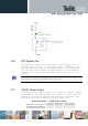
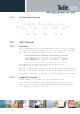
13.1.3. Low Pass Filter Example
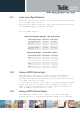
13.2. ADC Converter
13.2.1. Description
The on board ADCs are 10-bit converters. They are able to read
a voltage level in the range of 0-1.2 volts applied on the ADC
pin input and store and convert it into 10 bit word.
Min Max Units
Input Voltage
range
0 1.2 Volt
AD conversion - 10 bits
Resolution - < 1.2 mV
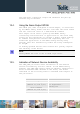
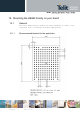
The HE863 Family module provides 3 Analog to Digital
Converters. The input lines are:
ADC_IN1 is available on BGA Ball R4 of the HE863 Family module.
ADC_IN2 is available on BGA Ball R5 of the HE863 Family module.
ADC_IN3 is available on BGA Ball S5 of the HE863 Family module.
13.2.2. Using ADC Converter
An AT command is available to use the ADC function.
The command is AT#ADC=1,2 The read value is expressed in mV
Refer to SW User Guide or AT Commands Reference Guide for the
full description of this function.