
User's Guide


HE863 Family Hardware User Guide
1vv0300891 Rev.5
- 2011-03-18
Reproduction forbidden without Telit Communications S.p.A’s. written authorization - All Rights
Reserved. Page 68 of 89
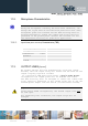
11.2. Microphone Characteristics
TIP:
Being the microphone circuitry the more noise sensitive, its
design and layout must be realized with particular care. Both
microphone paths are balanced and the OEM circuitry must be
balanced designed to reduce the common mode noise typically
generated on the ground plane. However the customer can use
the unbalanced circuitry for particular application.
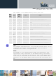
11.2.1. Input Lines (MIC1 and MIC2) Characteristics (TBD)
Line coupling
Line type
Coupling capacitor
Differential input
impedance
Differential input
voltage
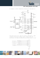
11.3. OUTPUT LINES (Speaker)
We suggest driving the load differentially from both output
drivers, thus the output swing will double and the need for the
output coupling capacitor avoided.
If a particular OEM application needs a Single Ended Output
configuration the output power will be reduced four times.
The OEM circuitry shall be designed to reduce the common mode
noise typically generated on the ground plane and to get the
maximum power output from the device (low resistance tracks).
(*) WARNING:
Using single ended configuration, the unused output line must
be left open.
Not respecting this constraint, the output stage will be
damaged.