
User's Manual


13
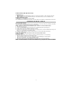
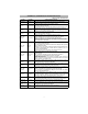
APPENDIX A: COMMUNICATOR TROUBLESHOOTING
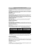
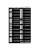
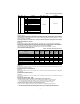
Table 5: Trouble LED indications
Trouble
indication
Possible
Causes
Trouble Possible Solution
No Indication No Power
• Check the power connections between the Panel and the Communicator.
• Confirm PC-LINK cable is properly installed between communicator and panel.
Yellow LED –
ON Solid
Insufficient
Signal Strength
• Confirm that GPRS network service is active in your area.
• Ensure the antenna is securely connected to the radio. Check antenna stub cable
is securely connected to the radio.
• If an external antenna is used ensure the antenna is securely screwed on to the
antenna cable connector. Check external antenna for damage or open/short.
Trouble LED –
2 Flashes
Panel
Supervision
Trouble
• Check Section [382]Toggle Option[5] is ON.(GPRS/Ethernet Module Enabled)
• Ensure the PC-LINK cable between the Panel and Communicator is connected
properly (not reversed) and is securely in place.
Yellow LED -
4 Flashes
Lockout
Trouble
• The SIM card has incorrect PIN programmed or has a PIN that the module does
not recognize. Replace the SIM card.
Yellow LED –
5 Flashes
GSM Trouble
• Confirm that GPRS service is available and active in your area.
• Check all antenna connections.
•Ensure
average
radio signal strength is CSQ
6
or higher. (See Table 4 ).
• Ensure the SIM card is properly inserted into the SIM card holder.
• Ensure the SIM card has been activated. (Could take up to 24 hrs after install).
• If this trouble persists, you must relocate the Panel (and Communicator) or install
an external antenna extension kit.
Yellow LED –
6 Flashes
Ethernet
Trouble
• Check with your ISP to confirm Internet service is active in your area.
• Ensure your Ethernet cable is securely inserted into the RJ45 jack of the Commu-
nicator and the Hub/Router/ Switch.
• Check the link light on the Hub/Router/ Switch is ON . If link light is OFF, try restart-
ing the Hub/Router/ Switch.
• If DHCP is used, ensure that the unit has an assigned IP address from the server.
In Panel Section [851] [992] verify a valid IP address is programmed. If not, con-
tact the Network administrator.
• If problem persists, replace the Ethernet cable and RJ45 connector.
Yellow LED –
7 Flashes
Receiver Not
Available
• Ensure that the Ethernet path has internet connectivity.
• If you are using a static IP address make sure the gateway and subnet mask are
entered correctly.
• If the network has a firewall, ensure the network has the programmed
outgoing ports open (Default UDP Port 3060 and Port 3065).
• Ensure that all the receivers are programmed for DHCP or have the proper IP
address and port number.
• Ensure the GPRS Receiver APNs have been programmed with the Access Point
Name provided by your GPRS provider.
Yellow LED –
8 Flashes
Receiver
Supervision
Trouble
• This trouble is indicated when supervision is enabled and the unit is not able to
successfully communicate with the receiver.
• If this trouble persists, contact your central station.
Yellow LED -
9 Flashes
FTC Trouble
• The unit has exhausted all communications attempts to all programmed receiver
for events generated by the Communicator.
• Restart the system, if trouble persists, contact your dealer.
Yellow LED –
10 Flashes
Connect24
Configuration
Failure
• This trouble is indicated when the SIM is active but there is no programming for
the unit.
• Ensure a profile has been programmed in Connect 24 for the SIM.
• You can confirm your programming by calling the Connect 24 VRU, or by logging
into the Connect24 VRU web site.
Yellow LED –
11 Flashes
Remote
Programming
• The LEDs will flash when a remote firmware upgrade is in progress over Ethernet
or GPRS. The LEDs will extinguish when update is complete.
• The LEDs will flash to indicate a remote programming session is active over
Ethernet or GPRS. The LEDs will extinguish when the session terminates.
Yellow LED –
12 Flashes
Module
Configuration
Trouble
This indication appears when Section [021] System Account Code or
Section [101]; [111]; [201]; and [211] Receiver Account Code have not been pro-
grammed. Ensure that a valid account code has been entered in these Sections.
All LEDs flash-
ing together
Boot Loader
Failed
Disconnect power, then reconnect power to the Communicator module.
Red and Yellow
LEDs flashing
together
Initialization
Sequence
The unit is still initializing please wait while the unit gets its programming and estab-
lishes a connection to all programmed receivers.
Note that this process may take several minutes.
Only Green
LEDs flashing
Hardware
Default Jumper
The hardware default jumper must be removed. See Figure 3.