
User's Manual


12
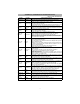
Network Activity LEDs (Red and Green)
(TL260GS-SM only)
• Ethernet Activity: Red LED will blink quickly once for Ethernet Transmit, or twice for Ethernet Receive.
• GPRS Activity: Green LED 2 will blink quickly once for GPRS Transmit, or twice for GPRS Receive.
Network Link LED (Yellow)
(TL260-SM only) See Figure 3 for location of LED.
The TL260-SM uses an additional Link LED on the board. LED is lit to indicate an active Ethernet connection.
.
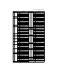
Factory Defaults Reset
You can reset the programming options for the Communicator to the factory settings by installing the hardware
jumper. Perform the following steps to reset the Communicator:
NOTE: A jumper is required on AUDIO/DEFAULT pins 4 and 5 to reset the hardware values.
1. Remove Panel front cover.
2. Locate the AUDIO/DEFAULT 5 pin connector on the Communicator board. (See Figure 3).
3. Apply a jumper to short the hardware default pins 4 and 5.
4. Remove AC and DC power from the panel and then reapply power to the Panel. Wait until the two green
LEDs on the Communicator begin flashing rapidly.
5. Remove the jumper from the hardware default pins 4 and 5. (Green LEDs will stop flashing).
6. Replace the Panel cover.
NOTE: Your Communicator has now been reset to the factory default values.
Firmware Update
The firmware of the device can be updated over GPRS or Ethernet (Remote or Local updating):
• When the firmware update begins, all 4 LEDs are ON.
• During the firmware update process, the LEDs will be cycled individually in a chaser pattern.
• After a successful update, the unit will automatically restart.
• Should the update fail, all 4 LEDs will flash ON, then OFF together at 1 second intervals.
NOTE: If the firmware update fails, restart the Communicator by cycling Power. For persistent update
failures, contact your dealer. For UL/ULC listed installations, only local firmware updates are allowed.
COMMUNICATOR RESET / UPDATE