
User's Manual


9
Install Network Cable (TL260-SM/TL260GS-SM only)
Route the CAT 5 Ethernet cable through back of the panel and plug it into the Communicator’s RJ45 jack.
Before leaving the premises the Ethernet communication lines must first be connected to an approved
(acceptable to local authorities) type NID, (UL installations, UL 60950 listed NID, for ULC installations
CAN/CSA C22.2. No. 60950-1 Certified NID). All wiring shall be performed according to the local
electrical codes.
6. Perform the following steps for initial power on of the panel with Communicator installed:
a. Reconnect the AC power, telephone line, and battery + connector to the panel. (the Communicator and
Panel will power up together).
b. Observe that the Communicator’s red and yellow LEDs are flashing together while it initializes. The red
and yellow LEDs will continue to flash until the Communicator has successfully communicated to all pro-
grammed receivers. If this is the first time the Communicator has been powered up in the panel, the mod-
ule will initiate communication to request programming remotely.
NOTE: Initialization may take several minutes to complete. red and yellow LEDs will flash together dur-
ing initialization. Do not continue to next step until the red and yellow LEDs have stopped flashing. (If
only the yellow LED is flashing, there is a Communicator trouble and the Green LEDs are not valid for
Communicator Placement Test). Correct trouble indicated by flashes on yellow LED before continuing.
(See Table 5 for troubleshooting assistance).
7. GS2060-SM/TL260GS-SM only: Perform the Communicator Placement Test on page 10.
8. Mount the Panel in final location indicated by placement test.
Domain Name Service (DNS) programming is not permitted in UL/ULC listed systems.
Keypad Data Display
• Section-Toggle Options: The number is displayed when Toggle is ON, the number is not displayed when
Toggle is OFF. (e.g., Toggle Options displays: [
--
3
--
6
--
]. Options 3 and 6 are ON, all others are OFF). Press-
ing keys 1 through 8 will alternately turn the Toggle ON and OFF.
• HEX/Decimal Data: Values that are provided with two defaults, separated by a “/” character, use the format:
hexadecimal followed by decimal equivalent (e.g., Default [0BF5/3061]). Hexadecimal numbers are shown,
with all leading zeroes, to the full field length defined for the number.
Entering HEX values at keypad
To enter HEX values at the keypad, you must press the
*
key before entering the HEX value. (e.g., to enter “
C
” at
the keypad, press
[*][3]
.
Entering ASCII Characters at keypad
1. Press [*] and use scroll buttons [<] [>] to display “ASCII Entry” on the LCD screen.
2. Press [*] to select ASCII entry mode.
3. Use the [<] [>] scroll keys to display the character you want and press [*] to save and exit ASCII.
4. Repeat the steps above to enter another ASCII character.
PC1616/1832/1864 Initial Programming
Perform the following steps to ensure that the Communicator and the Panel work together as intended.
These Sections must be programmed at the panel keypad. Enter
[*][8][Installer Code][Section Number]
. Record
any values that are modified from their default, in the appropriate Worksheets for the Panel or Communicator.
1. In Panel Section [167] program 060 (seconds).
2. In Panel Section [382] set Option [5] ON
NOTE: If this option is OFF, the yellow status LED on the Communicator will indicate ‘Panel Supervision Trou-
ble’ (2 flashes) and the unit can not be programmed via the PC-LINK cable.
3. In Panel Section [383] [2] set Option [7] ON.
4. In Panel Section [383] [2] set Option [8] ON for CID, or OFF for SIA.
5. A valid Account Number must be entered in Communicator Section [851][021]. See Programming Section.
NOTE: DSC recommends using the same Account Number for Panel and Communicator.
6. In Panel Sections [301], [302], and [303], program the central station telephone number that will be used for
the GPRS/Ethernet Communicator. Valid entries are:
a. A valid telephone number; signals will be routed to the central station using the Public Switched Tele-
phone Network (PSTN).
b. DCAA (Receiver 0); signals will be routed to GPRS/Ethernet Receivers 1 - 4 depending on programming
Toggle Options in Communicator Section [851][006].
c. Panel Section [301] sets the Primary communication path, and may be configured as either PSTN or
Communicator routing. Panel Section [302] is redundant, and Panel Section [303] is the backup tele-
phone number for Panel Section [301]. Refer to the Panel manual for additional information.
NOTE: The leading digit ‘D’ (dial tone detection) in the telephone number is pre-programmed.
7. In Panel Section [350], program the communication format as: CID (03) or SIA FSK (04).
NOTE: If any of the Panel telephone numbers have been set to DCAA, section [350] must be set to (04).
8. In Panel Sections [351] - [376], program the Communicator call direction options. Refer to the Panel Installa-
tion Manual for details on setting these options.
9. In Panel Section [401] set Toggle Option [2] ‘User Enable DLS’ to ON in order to perform panel DLS session
through GPRS or Ethernet.
NOTE: Before leaving the premises, the installer should verify all programmed communications paths.
See Programming Options Section [851][901] to send immediate test transmissions.
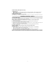
Communicator Troubles displayed on a PC1616/1832/1864
The General System trouble is the only trouble that will appear on the keypad Liquid Crystal Display (LCD)
when encountered by a Communicator installed in a PC1616/1832/1864. For more information about the trou-
ble on the Communicator module refer to the panel event buffer. Log entry will show Fault or Restore for each
of the following events:
INITIAL PANEL PROGRAMMING