
User's Manual


8
Keybus Connection for ADT Pulse
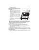
4. Install the Keybus cable as follows:
WARNING: DO NOT CONNECT KEYBUS RED OR BLK WIRES TO THE PANEL OR
THE COMMUNICATOR TERMINAL BLOCKS.
a. Attach a wire from the Communicator YEL terminal to the panel YEL terminal.
b. Attach a wire from the Communicator GRN terminal to the panel GRN terminal.
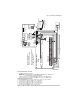
RS-422 Connection for ADT Pulse
At the Communicator inside the Panel, attach the previously run cable as follows:
1. Securely fasten the TX+ wire to RX+ on the terminal block.
2. Securely fasten the TX- wire to RX- on the terminal block.
3. Securely fasten the RX+ wire to TX+ on the terminal block.
4. Securely fasten the RX- wire to TX- on the terminal block.
5. Securely fasten the GND wire on the terminal block .
NOTE: The GND connection is optional, DSC recommends connecting GND at both ends of cable.
DG009546
AUDIO/ DEFAULT
DSC
UA585
PC-LINK
PC- LI NK
GND
TL260-SM
TL260GS-SM
GS2060-SM
AC
AC
Z1 COM Z2 Z3 COM Z4 Z5 COM Z6 Z7 COM Z8
AUX+
BELL +
PGM1 PGM3
RING
T-1
PC1616/1832/1864
GSM Radio
RX 1 & RX 2
+
-
UA503
1
To ex t e r n al antenna
Input Ratings from Bell +:
+11.1V ~ +12.6 VDC
100mA standby; 400mA alarm
DSC Panel min power requirements:
- 16 VAC 40 VA transformer;
- 12 VDC 7Ah battery
+
-
External Bell/Siren
Black
Black
Jumper pins 4 and 5
to reset.
L
o
c
k
1
GRN
RS-422
To ADT iHub
Maximum cable length
305 m (1,000 ft)
From NID
(GS2060-SM/TL260GS-SM)
Use only CAT5
Supervised
RJ-45
YEL
COM
PWR
GRN
YEL
TIP
R-1
BLK
RED
AUX -
BELL -
EGND
Do NOT
connect
Red or Black
Keybus wires!
TX+
GND
TX-
RX+
RX-
SHLD
Green
Yell ow
SIM
Network Link
(TL260-SM only)
YELLOW
XX
PGM2 PGM4
Maximum cable length
100 m (328 ft)
PWR
REV 0 1
Figure 3 Communicator Wiring Diagram