Alarm Communicator GS2060-SM GPRS Cellular Communicator TL260-SM Ethernet/Internet Communicator TL260GS-SM Ethernet/Internet and GPRS Dual-Path Communicator v2.0 Installation Manual Warning: This manual contains information on limitations regarding product use and function and information on the limitations as to liability of the manufacturer.
TABLE OF CONTENTS GENERAL . . . . . . . . . . . . . . . . . . . . . . . . . . . . . . . . . . . . . . . . . . . . . . . . . . . . . . . . . . . . . . . . . . . . . . . . . . . . . . . . . . . 3 Panel Mounting . . . . . . . . . . . . . . . . . . . . . . . . . . . . . . . . . . . . . . . . . . . . . . . . . . . . . . . . . . . . . . . . . . . . . . . . . . . . . . . . . . . . . . Features . . . . . . . . . . . . . . . . . . . . . . . . . . . . . . . . . . . . . . . . . . . . . . . . . . . . . . . . . . . . .
WARNING Please Read Carefully Note to Installers This Warning contains vital information. As the only individual in contact with system users, it is the installer’s responsibility to bring each item in this Warning to the attention of all users of this system. System Failures This system has been carefully designed to be as effective as possible. There are circumstances, however, involving fire, burglary, or other types of emergencies where it may not provide protection.
GENERAL IMPORTANT This installation manual shall be used in conjunction with the Alarm Controller Power Panel manual. All the safety instructions specified within that manual shall be observed. (or equivalent). The Alarm Controller Power Panel is referenced as the “panel” throughout this document. The General Packet Radio Service (GPRS)/Ethernet Communicator is fixed, wall-mounted unit, located inside the panel, and shall be installed in the location specified in these instructions.
UL/ULC Installation Requirements NOTE: For equipment used at the protected premises and intended to facilitate IP communications (hubs, routers, NIDs, Digital Subscriber Line (DSL), Cable modems), 24 hour back-up power is required. Where such cannot be facilitated, a secondary (back-up) communication channel is required. Domain Name Service (DNS) programming is not permitted in UL/ULC listed systems.
Table 2: Compatible Receivers, and Panels Communicator GS2060-SM Receiver/ Panel Receiver TL260-SM TL260GS-SM Panel Description • • • • • • • Sur-Gard System I Receiver, version 1.30+ Sur-Gard System II Receiver, version 2.10+ Sur-Gard SG-DRL3-IP, version 2.30+ (for Sur-Gard System III Receiver) Sur-Gard SG-DRL4-IP version 1.20+ (for Sur-Gard System IV Receiver) Power Series PC1616, version 4.5+ Power Series PC1832, version 4.5+ Power Series PC1864, version 4.
Installing the Ethernet Cable (TL260-SM/TL260GS-SM only) A Category 5 (CAT 5) ethernet cable must be run from a source with Ethernet/Internet connectivity to the Communicator module, inside the Panel. The Communicator end of the cable must be terminated with an RJ45 plug, which will connect to the Communicator’s RJ45 jack after the Communicator is installed.
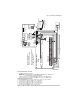
UA58 5 a. Attach one end of the PC-LINK cable to the panel PC-LINK header on the panel (red wire goes on Pin 1 of the panel PC-LINK header). b. Insert the assembled Communicator into the panel. NOTE: Ensure that the threaded antenna connection Figure 2 PC1616/1832/1864 Control Panel point is visible through the knockout hole at the top right of the panel. c.
- External Bell/Siren + Maximum cable length 100 m (328 ft) From NID (GS2060-SM/TL260GS-SM) Use only CAT5 Supervised RJ-45 (TL260-SM only) YELLOW RING TIP T-1 R-1 1 PC-LINK Black Black Yellow Do NOT connect Red or Black Keybus wires! DG009546 Keybus Connection for ADT Pulse 4. Install the Keybus cable as follows: WARNING: DO NOT CONNECT KEYBUS RED OR BLK WIRES TO THE PANEL OR THE COMMUNICATOR TERMINAL BLOCKS. a. Attach a wire from the Communicator YEL terminal to the panel YEL terminal. b.
Install Network Cable (TL260-SM/TL260GS-SM only) Route the CAT 5 Ethernet cable through back of the panel and plug it into the Communicator’s RJ45 jack. Before leaving the premises the Ethernet communication lines must first be connected to an approved (acceptable to local authorities) type NID, (UL installations, UL 60950 listed NID, for ULC installations CAN/CSA C22.2. No. 60950-1 Certified NID). All wiring shall be performed according to the local electrical codes. 6.
• • • T-LINK Network Fault/Restore: This log will occur for the following trouble conditions: SIM Lock Trouble, GSM Trouble, Ethernet Trouble, or Connect24 Configuration Trouble. T-LINK Receiver Trouble/Restore: This log will occur for the following trouble conditions: Receiver Not Available Trouble, Receiver Supervision Trouble, or Failure to Communicate (FTC) Trouble. T-LINK Comm.
SIM Lock Trouble (4 Flashes) This trouble will signify that the SIM lock feature has been enabled and the unit has not been programmed with the correct PIN for the SIM card. GSM Trouble (5 Flashes) This trouble is indicated for any of the following 4 conditions: 1. Radio Failure: Trouble is indicated after 8 failed attempts to communicate with the GPRS radio. 2. SIM Failure:Trouble is indicated after 10 failed +CPIN commands. 3.
Network Activity LEDs (Red and Green) (TL260GS-SM only) • Ethernet Activity: Red LED will blink quickly once for Ethernet Transmit, or twice for Ethernet Receive. • GPRS Activity: Green LED 2 will blink quickly once for GPRS Transmit, or twice for GPRS Receive. Network Link LED (Yellow) (TL260-SM only) See Figure 3 for location of LED. The TL260-SM uses an additional Link LED on the board. LED is lit to indicate an active Ethernet connection. .
APPENDIX A: COMMUNICATOR TROUBLESHOOTING Table 5: Trouble LED indications Trouble indication Possible Causes No Indication No Power Yellow LED – ON Solid Insufficient Signal Strength Trouble LED – 2 Flashes Yellow LED 4 Flashes Panel Supervision Trouble Lockout Trouble Yellow LED – 5 Flashes GSM Trouble Yellow LED – 6 Flashes Ethernet Trouble Yellow LED – 7 Flashes Receiver Not Available Yellow LED – 8 Flashes Receiver Supervision Trouble Yellow LED 9 Flashes FTC Trouble Yellow LED – 10 Fl
COMMUNICATOR PROGRAMMING SECTIONS The Programming Sections in this document are accessed via panel Section for Ethernet/GPRS Programming. Enter: [*][8][installer code][851][# ##], Where # ## is the 3 digit Section number referenced in this document. The Programming Worksheets at the end of this document can be used to record the new values when programming changes have been made from the default values. Default values are provided for each Section. Programming Sections cannot be modified from the keypad.
OFF: GPRS Receiver 1 will not be supervised. When disabled, heartbeat is not sent to the receiver. NOTE: GPRS Receiver 2 can not be supervised. [3] Supervision Type Default (OFF) ON: Heartbeat 1 (Commercial Supervision). This supervision type is suitable for applications where swap detection is required on the supervisory packet. OFF: Heartbeat 2 (Residential Supervision). This supervision type is suitable for applications where supervision of the communication path to the receiver is required.
[008] DNS Server IP 2 Programming this Section is not permitted on a UL/ULC listed system. Default (000.000.000.000) Enter the IP address for DNS Server 2. Format is 4 fields, each field is a 3 digit decimal. Valid range: 000-255. NOTE: If no value is programmed and DHCP is used, the DHCP Server will assign this value. If an address is programmed and DHCP is used, the address that you program will be used instead of the DHCP address.
Table 7: Time Zone Offset (Continued) HEX 1D 1F Offset Std Hours Abbrev EST COT ECT -5 PET ACT -4.5 VST 21 -4 AST CLST BWST SLT PYT JFST GYT FKST BOT 23 -3.5 25 29 -3 -2 Location HEX Eastern Standard Time Colombia Time Ecuador Time Peru Time Acre Time -1 31 0 35 +1 39 +2 3D +3 3F +3.
Table 7: Time Zone Offset (Continued) HEX 45 Offset Std Hours Abbrev CAST WKST PKT YEKT UZT TMT TJT +5 TFT MVT MAWT KGT HMT DAVT Location HEX Chinese Atlantic Standard Time West Kazakhstan Standard Time Pakistan Time Yekaterinburg Time Uzbekistan Time Turkmenistan Time Tajikistan Time French Southern and Antarctic Time Maldives Time Mawson Time Kyrgyzstan Time Heard and McDonald Island Time Davis Time Offset Std Hours Abbrev Location Reserved 70 - FF [021] Account Code Default (FFFFFF) The account
Alternate Test Transmission: Alternate Test Transmission can be enabled or disabled in Section [005] Toggle Option [7]. [026] Ethernet 1 Transmission Default (FF) Program 00 to disable this event transmission or FF to enable. See System Test Options (above) for details on settings. [027] Ethernet 2 Transmission Default (00) Program 00 to disable this event transmission or FF to enable. See System Test Options (above) for details on settings.
[105] Ethernet Receiver 1 Local Port Default (0BF4/3060) Use this Section to set the value of the local outgoing port. Set the value of this port when your installation is located behind a firewall and must be assigned a particular port number as determined by your central station system administrator. Valid range: 0000 - FFFF. [106] Ethernet Receiver 1 Domain Name Default () Enter the Domain Name as 32 ASCII characters. Programming this Section is not permitted on a UL/ULC listed system.
GPRS Receiver 1 Options [201] GPRS Receiver 1 Account Code Default (0000000000) The account code is used by the central station to distinguish between transmitters. This account code is used when transmitting heartbeat signals to the central station receiver. Signals received from the control panel will use the control panel account number. Valid range: 0000000001 - FFFFFFFFFE. Programming this Section as all 0 or all F will cause a Module Configuration Trouble (yellow LED = 12 flashes).
GPRS Options [221] GPRS Public Access Point Name Default ( ) When the Communicator is operating on a private APN, use this Section to select a public APN for DLS and Remote Firmware Update. This information is available from your network carrier. The APN identifies the public GPRS network that the Communicator will connect to. [222] GPRS Login User Name Default ( ) Some network carriers require you to provide login credentials when connecting to an APN. Program your login User name here.
[658] Interactive Access Point Name 1 Default ( ) This section is programmed as 32 character ASCII. Receiver 1 shall use this APN to connect to the Interactive network. Two sockets are opened, one for each receiver. If both APNs are left blank, the unit will eventually display a Receiver not Available Trouble. [659] Interactive Access Point Name 2 Default ( ) This section is programmed as 32 character ASCII. Receiver 2 shall use this APN for Interactive.
[673] Lifestyle Zone 9 - 16 Toggle Options The default for each Lifestyle Zone Toggle is ON. Table 14: Lifestyle Zone 9 - 16 Toggle TOGGLE ZONE 01 9 02 10 03 11 04 12 05 13 06 14 07 15 08 16 [674] Lifestyle Zone 17 - 24 Toggle Options The default for each Lifestyle Zone Toggle is ON. Table 15: Lifestyle Zone 17 - 24 Toggle TOGGLE ZONE 01 17 02 18 03 19 04 20 05 21 06 22 07 23 08 24 [675] Lifestyle Zone 25 - 32 Toggle Options The default for each Lifestyle Zone Toggle is ON.
[683] Notification Zone 9 - 16 Toggle Options The default for each Notification Zone Toggle is OFF. Table 22: Notification Zone 9 - 16 Toggle TOGGLE ZONE 01 9 02 10 03 11 04 12 05 13 06 14 07 15 08 16 [684] Notification Zone 17 - 24 Toggle Options The default for each Notification Zone Toggle is OFF.
[991] Firmware Version This Section will display the current firmware version of the device. Update worksheets with new version after a flash update is completed. [992] Ethernet IP Address This Section will display the IP address of the Ethernet connection. This value is programmed in Section [001] or assigned by DHCP. [993] Ethernet Gateway Address This Section will display the IP address of the Ethernet Gateway. This value is programmed in Section [003] or assigned by DHCP.
COMMUNICATOR PROGRAMMING WORKSHEETS System Options [021] Account Code Default (FFFFFF) [001] Ethernet IP Address |____|____|____|____|____|____| Default (000.000.000.000) |____|____|____||____|____|____||____|____|____|____|____|____| [022] Communications Format [002] Ethernet IP Subnet Mask Default (04) Program 03 (CID), 04 (SIA). Default (255.255.255.
[206] GPRS Receiver 1 Domain Name Default ( ) Programming not permitted on UL/ULC listed system. 32 Character ASCII characters. ____________________________________ [105] Ethernet Receiver 1 Local Port Default (0BF4/3060) Valid range: 0000 - FFFF. |____|____|____|____| [106] Ethernet Receiver 1 Domain Name Default () 32 ASCII characters. GPRS Receiver 2 Options Programming not permitted on UL/ULC listed system.
[675] Lifestyle Zone 25 - 32 Toggle Options [652] Interactive Access Code Default (1234) |____|____|____|____|____|____|____|____| |____|____|____|____| 25 26 27 28 29 [653] Interactive IP Address Default (000.000.000.
Receiver Diagnostic Testing [994] GPRS IP Address [901] Diagnostic Test Transmission |____|____|____||____|____|____||____|____|____|____|____|____| |___| [1] Ethernet 1 Default (OFF). [995] SIM Number ____________________________________ |___| [2] Ethernet 2 Default (OFF). [996] GSM Telephone Number |___| [3] GPRS 1 Default (OFF). |___| [4] GPRS 2 Default (OFF). This number is required for DLS, and Firmware upgrades.
END USER LICENCE AGREEMENT IMPORTANT - READ CAREFULLY: DSC Software purchased with or without Products and Components is copyrighted and is purchased under the following license terms: This End-User License Agreement (“EULA”) is a legal agreement between You (the company, individual or entity who acquired the Software and any related Hardware) and Digital Security Controls, a division of Tyco Safety Products Canada Ltd.
Limited Warranty ered by this warranty, or otherwise out of warranty Digital Security Controls warrants the original purdue to age, misuse, or damage shall be evaluated, chaser that for a period of twelve months from the and a repair estimate shall be provided. No repair date of purchase, the product shall be free of defects work will be performed until a valid purchase order is in materials and workmanship under normal use.
FCC Compliance Statement CAUTION: Changes or modifications not expressly approved by the manufacturer could void your authority to use this equipment. This equipment has been tested and found to comply with the limits for a Class B digital device, pursuant to Part 15 of the FCC Rules. These limits are designed to provide reasonable protection against harmful interference in a residential installation.