LC-151 Dual-Tech Motion Sensor (Single Element PIR & Microwave) with optional Pet Immunity INSTALLATION INSTRUCTIONS & USER MANUAL P/N: 7131720 ver.
1 General...................................................................................................................................... 3 2 Features .................................................................................................................................... 3 3 Assembly description................................................................................................................. 4 4 Detection Pattern........................................................
1 General The LC-151 is a unique motion detector utilizing a single passive infra-red element and Microwave technology for use outdoors in harsh environments. The LC-151 is designed for outdoor use in the most severe and climatic conditions and may also accommodate pets with the addition of optional pet immunity lenses. High reliability is achieved by combining both dual tech hardware with highly sophisticated software, greatly reducing the possibility of false alarms.
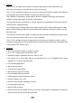
3 Assembly description The LC-151 is a robust yet small detector which includes a large LED indicator that can be easily observed from long distances to provide indication of intrusion. Using the supplied mounting bracket, the LC-151 can be easily mounted to walls using the provided mounting screws. For installations requiring the detection beam to be adjusted horizontally or vertically to obtain the desired field of protection use the LC-B1-15X Outdoor Mounting Bracket pictured below.
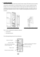
4 Detection Pattern The LC-151 has a 90° top view PIR and MW detection pattern with over 15m detection distance (when installed at 2.4m above the ground surface).
LC-L3-15X Curtain Lens (sold separately) The LC-151 can differentiate between pets and human bodies and alert accordingly by utilizing microwave movement detection combined with a PIR detection beam. An intrusion is defined by the PIR detection beam being crossed and a microwave detection occurring, causing an alarm. No alarm will be generated if only the PIR detection beam is crossed or if only a microwave detection occurs.
5 Selecting mounting location The installation of the LC-151 requires a solid, level base for the mounting bracket and must be located in a manner that when the detector is mounted, it is facing the center of the desired detection zone. The protected area must be free from obstacles like walls, fences, trees, ditches and other microwave detectors. Choose a location most likely to intercept an intruder according to detection pattern on page 5.
6 Detector Installation Important! Prior to installation, read both “Operation” and “Selecting the mounting location” sections carefully. 1. Install the detector in such manner that the intruder is 2. The detector is to be installed at height of 1.8 to 2.4 most likely to cross the detection area from side to side. meters (ideally 2.1m) 3. Make sure to attach the metal bracket to a leveled 4.
7. Release the detector body from the metal bracket by 8. Attach the rear bracket to the wall using mounting pulling the detector up and out. screws. 9. Insert wires through provided access hole and wiring 10. Attach the sealing sponge pad to the wire opening channels. from the rear side after the wires have been connected and prior to final product affixing to the mounted bracket. 11. Place the detector on the mounting bracket from top 12.
7 Terminal Block Connections Terminal 1 - Marked “+” (+12V) - Connect to a positive Voltage of 9.6 -16Vdc source (usually from the control panel) Terminal 2 - Marked “-” (GND) - Connect to the ground of the control panel. Terminals 3 & 4 - Marked “TAMPER” - If a Tamper function is required connect these Terminals to a normally closed 24-Hour Tamper Zone on the control panel.
8 Settings & Adjustments 8.1 Detection beam direction The LC-151 detection beam direction is fixed. As a result, it is recommended to face the intrusion area with the detector. 8.2 Sensitivity Adjustment The calibration of detector sensitivity is performed by a single sensitivity potentiometer and a Microwave intensity jumper. Changing the PIR sensitivity and microwave intensity affects immunity to environmental noises and allows the detector to operate without nuisance alarms in noisier environments.
Environment type Potentiometer position MW jumper position Low risk At position 5 H Risk Between positions H 3 and 4 High risk Between positions L 4 and 5 Very high risk Between positions L 3 and 4 Noisy area Between positions L 2 and 3 Extremely Noisy area At position 1 L Note: Adjust sensitivity according to environmental conditions! • Low risk: very stable environment without interference from parking garages, parking space, playgrounds, football fields, service roads, etc.
When the LED jumper is in the "ON" position the LEDs will be active. When the LED jumper is in the "OFF" position, the LEDs will not activate. Detection LEDs LEDs Control jumper (Factory setting: ON) • Place the top cover to the base and close it using the bottom screw.
9 Operation Note! Connect the LC-151 to a positive Voltage output of 9.6 -16VDC source. Use only a listed power limited source. The detector shall be provided with minimum of 4 hours of standby power from either a listed compatible control unit or power supply. The detector begins a 30 second warm up period once connected to power. If the LEDs are enabled, they will sequentially flash from left to right for the duration of the 30 seconds warm up period.
12 Specifications Detection Method Microwave Frequency Power Input Current Draw Temp Compensation Alarm Period RF Immunity PIR AND MW X-band (9.9GHz / 10.525GHz / 10.687GHz) 9.6 to 16Vdc Active: 24mA (±5%); Standby: 21mA (±5%) Dual slope temperature compensation 2 sec (±0.5sec) Form C (NC, NO, Common) 28Vdc 0.1 A with 10 Ohm Two Switches N.C 28Vdc 0.
Limited Warranty Digital Security Controls warrants that for a period of 12 months from the date of purchase, the product shall be free of defects in materials and workmanship under normal use and that in fulfillment of any breach of such warranty, Digital Security Controls shall, at its option, repair or replace the defective equipment upon return of the equipment to its repair depot.