
User's Manual
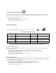
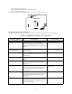
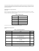
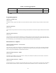
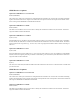
Table Of Contents
- TL260GS / TL265GS
- TL260GS / TL265GS
- Installation Manual
- Limited Warranty
- WARNING
- Note to Installers
- System Failures
- Criminal Knowledge
- Access by Intruders
- Power Failure
- Failure of Replaceable Batteries
- Compromise of Radio Frequency (Wireless) Devices
- Smoke Detectors
- Motion Detectors
- Warning Devices
- Telephone Lines
- Insufficient Time
- Component Failure
- Inadequate Testing
- Security and Insurance
- Warning
- FCC
- Introduction
- 1 . On your hard drive, locate the laptop’s IP address. Retrieve the number of the listening port; this is assigned by the application. You should also have on hand the Communicator’s phone number.
- 2 . Using this phone number send the Communicator an 18-digit SMS text message. This SMS text message is to be configured as: ! + IP address + Port number, without stops or spaces (e.g. !11122233344412345). Note that if you intend to use a port numbe...
- 3 . With an existing installation of DLS IV downloading software on your laptop, you now have the ability to program the Communicator using the GUI on the screen. See Options on page 23 for detailed programming information. Also, please refer to your...
- Models
- Features
- Technical Specifications
- Ratings
- Compatibility
- Table 2: Compatible Receivers and Control Panels
- INSTALLING THE GSM / ETHERNET COMMUNICATOR
- 1 . Wire the telephone line, if available.
- 2 . Wire the PC9155 panel (but not the Communicator).
- 3 . Turn on the PC9155 panel. Program the panel’s telephone number, account code, format, GS / IP module enable, and the communication path priority (i.e. PSTN > Ethernet > GRPS).
- 4 . Turn off the panel.
- 5 . Wire the Communicator through the PC-Link.
- 6 . Proceed to CONNECT 24 Activation Information below.
- 7 . Turn on the panel. Wait for the initialization of the Communicator.
- 1 . Assemble the Communicator
- 2 . Install the Communicator module into the Cabinet
- 3 . Turn on the panel and check signal strength.
- 1 . Attach the Communicator to the inside of the PC9155 control panel cabinet if not already present.
- 2 . Turn on the PC9155 cabinet and check signal strength.
- 1 . Program the hexadecimal digits (DCAA) in the telephone number that will be used to contact the GSM / Ethernet Communicator (panel Options 301, 302, 303, ‘Telephone Phone Number Programming’).
- 2 . In Option 350, program the communication format as SIA FSK.
- 3 . In Options 351 through Option 376, program the call direction sub-options for the phone number being used to communicate using the GSM / Ethernet Communicator.
- 4 . Option 382, sub-option 5 must be set to ON.
- STATUS LEDs
- Trouble Status LED
- Network Connection Status LED
- Signal Strength LEDs
- Table 4: Radio Signal Strength
- 1 . Turn off the power to the Communicator by physically unplugging the unit from its power supply.
- 2 . Attach one end of the extension cable to the Communicator and the other end to the antenna itself.
- 3 . Reattach the power supply and turn on.
- 4 . Move the antenna around until you have received a strong signal.
- 5 . Mount the antenna bracket at that location.
- 1 . Locate the set of five vertically aligned pins in the middle of the Communicator board.
- 2 . Counting from the bottom, the first three pins are reserved for future use. You may discount these.
- 3 . The final two pins require a jumper in order to reset the hardware values.
- 4 . Turn off power to the Communicator.
- 5 . Apply the jumper to the two pins.
- 6 . Turn on power to the Communicator. Wait for ten seconds.
- 7 . Remove the jumper from the pins.
- Table 5: Communicator Troubles on a 9155 Panel
- Table 4: Radio Signal Strength
- Options
- Programming Worksheets

25
NOTE: *Receivers 1 and 3 can be supervised; if enabled, heartbeats are sent. Receivers 2 and 4 cannot be super-
vised.
Programming Options
Option 011: Installer Code
Default (CAFE)
This option is used to program the installer code of the Communicator module. Valid entries range from 0000 to FFFF hexadeci-
mal.
Option 012: DLS Port
Default (3062)
The DLS Port is the port DLSV will use when connecting to the Communicator. Valid entries range from 0000 to FFFF hexadeci-
mal.
Option 013: DLS Local Port
Default (3063)
The DLS local port is used when the Communicator is connecting to DLSV. You can use this option to set the value of the local
outgoing port. Set the value of this port if your installation is located behind a firewall and must be assigned a particular port num-
ber, as determined by your network administrator. Valid entries range from 0000 to FFFF hexadecimal.
Ethernet Receiver 1 Options
Option 101: Ethernet Receiver 1 Account Code
Default (0000FFFFFF)
The account code is used by the central station to distinguish between transmitters. This account code is used when transmitting
signals to the central station receiver. Signals received from the control panel will use the control panel account number. Valid
entries will range from 0000000000 to FFFFFFFFFF hexadecimal.
Option 102: Ethernet Receiver 1 DNIS
Default (000000)
The DNIS is used in addition to the Account Code to to identify the Communicator module as the central station. Valid entries
range from 000000 to 0FFFFF hexadecimal.
Option 103: Ethernet Receiver 1 Address
Default (0.0.0.0)
Enter the Ethernet receiver 1 IP address. This information will be provided by your central station. Note that when a valid address
has been entered, the Ethernet will be considered to be enabled and will communicate events over the Ethernet channel. The
Bit 8 Reserved Disabled (Off)
Table 7: System Toggle Options
Valid Data Range Effect Default