
User's Manual
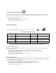
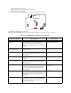
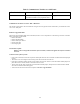
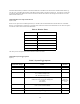
Table Of Contents
- TL260GS / TL265GS
- TL260GS / TL265GS
- Installation Manual
- Limited Warranty
- WARNING
- Note to Installers
- System Failures
- Criminal Knowledge
- Access by Intruders
- Power Failure
- Failure of Replaceable Batteries
- Compromise of Radio Frequency (Wireless) Devices
- Smoke Detectors
- Motion Detectors
- Warning Devices
- Telephone Lines
- Insufficient Time
- Component Failure
- Inadequate Testing
- Security and Insurance
- Warning
- FCC
- Introduction
- 1 . On your hard drive, locate the laptop’s IP address. Retrieve the number of the listening port; this is assigned by the application. You should also have on hand the Communicator’s phone number.
- 2 . Using this phone number send the Communicator an 18-digit SMS text message. This SMS text message is to be configured as: ! + IP address + Port number, without stops or spaces (e.g. !11122233344412345). Note that if you intend to use a port numbe...
- 3 . With an existing installation of DLS IV downloading software on your laptop, you now have the ability to program the Communicator using the GUI on the screen. See Options on page 23 for detailed programming information. Also, please refer to your...
- Models
- Features
- Technical Specifications
- Ratings
- Compatibility
- Table 2: Compatible Receivers and Control Panels
- INSTALLING THE GSM / ETHERNET COMMUNICATOR
- 1 . Wire the telephone line, if available.
- 2 . Wire the PC9155 panel (but not the Communicator).
- 3 . Turn on the PC9155 panel. Program the panel’s telephone number, account code, format, GS / IP module enable, and the communication path priority (i.e. PSTN > Ethernet > GRPS).
- 4 . Turn off the panel.
- 5 . Wire the Communicator through the PC-Link.
- 6 . Proceed to CONNECT 24 Activation Information below.
- 7 . Turn on the panel. Wait for the initialization of the Communicator.
- 1 . Assemble the Communicator
- 2 . Install the Communicator module into the Cabinet
- 3 . Turn on the panel and check signal strength.
- 1 . Attach the Communicator to the inside of the PC9155 control panel cabinet if not already present.
- 2 . Turn on the PC9155 cabinet and check signal strength.
- 1 . Program the hexadecimal digits (DCAA) in the telephone number that will be used to contact the GSM / Ethernet Communicator (panel Options 301, 302, 303, ‘Telephone Phone Number Programming’).
- 2 . In Option 350, program the communication format as SIA FSK.
- 3 . In Options 351 through Option 376, program the call direction sub-options for the phone number being used to communicate using the GSM / Ethernet Communicator.
- 4 . Option 382, sub-option 5 must be set to ON.
- STATUS LEDs
- Trouble Status LED
- Network Connection Status LED
- Signal Strength LEDs
- Table 4: Radio Signal Strength
- 1 . Turn off the power to the Communicator by physically unplugging the unit from its power supply.
- 2 . Attach one end of the extension cable to the Communicator and the other end to the antenna itself.
- 3 . Reattach the power supply and turn on.
- 4 . Move the antenna around until you have received a strong signal.
- 5 . Mount the antenna bracket at that location.
- 1 . Locate the set of five vertically aligned pins in the middle of the Communicator board.
- 2 . Counting from the bottom, the first three pins are reserved for future use. You may discount these.
- 3 . The final two pins require a jumper in order to reset the hardware values.
- 4 . Turn off power to the Communicator.
- 5 . Apply the jumper to the two pins.
- 6 . Turn on power to the Communicator. Wait for ten seconds.
- 7 . Remove the jumper from the pins.
- Table 5: Communicator Troubles on a 9155 Panel
- Table 4: Radio Signal Strength
- Options
- Programming Worksheets

22
Communicator Troubles on a 1616 / 1832 / 1864 Panel
The General System trouble is the sole trouble that will appear on the keypad LCD when encountered by a Communicator on the
1616 / 1832 / 1864 panel.
Firmware Upgrade Default
The firmware upgrade default differs from a full default, in that it is not as comprehensive. The following sections do not default
during a Firmware Upgrade Default:
• Ethernet IP Address
• Ethernet IP Subnet Mask
• Ethernet Gateway IP Address
• DLS Incoming Port
• DLS Outgoing Port
UL Firmware Update
NOTE: In order to comply with UL when this option is enabled, a remote flash upgrade will require an installer to
be on-site.
UL Remote Flash Update Operation
• If this option is enabled, the unit will not perform a flash update unless the unit is restarted with the hardware default jumper
in place.
• The remote server will configure the TFTP settings in the device and will restart the unit.
• If this option is enabled, restarting the unit will not initiate a TFTP session. However, when the hardware default jumper is in
place and the unit is restarted, the unit will initiate the TFTP session.
• The first reset after the TFTP session will ignore the hardware default jumper; subsequent resets with the hardware default
will result in a hardware default taking place.
• At the end of the TFTP session the unit shall perform a Firmware Upgrade Default.
Loss of Time and Date If power was lost completely (AC and battery), the
time and date will need to be re-programmed. Press *.
Re-program Time and Date
Table 5: Communicator Troubles on a 9155 Panel
Trouble Condition Description User Action