
User's Manual
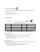
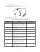
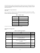
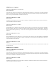
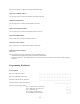
Table Of Contents
- TL260GS / TL265GS
- TL260GS / TL265GS
- Installation Manual
- Limited Warranty
- WARNING
- Note to Installers
- System Failures
- Criminal Knowledge
- Access by Intruders
- Power Failure
- Failure of Replaceable Batteries
- Compromise of Radio Frequency (Wireless) Devices
- Smoke Detectors
- Motion Detectors
- Warning Devices
- Telephone Lines
- Insufficient Time
- Component Failure
- Inadequate Testing
- Security and Insurance
- Warning
- FCC
- Introduction
- 1 . On your hard drive, locate the laptop’s IP address. Retrieve the number of the listening port; this is assigned by the application. You should also have on hand the Communicator’s phone number.
- 2 . Using this phone number send the Communicator an 18-digit SMS text message. This SMS text message is to be configured as: ! + IP address + Port number, without stops or spaces (e.g. !11122233344412345). Note that if you intend to use a port numbe...
- 3 . With an existing installation of DLS IV downloading software on your laptop, you now have the ability to program the Communicator using the GUI on the screen. See Options on page 23 for detailed programming information. Also, please refer to your...
- Models
- Features
- Technical Specifications
- Ratings
- Compatibility
- Table 2: Compatible Receivers and Control Panels
- INSTALLING THE GSM / ETHERNET COMMUNICATOR
- 1 . Wire the telephone line, if available.
- 2 . Wire the PC9155 panel (but not the Communicator).
- 3 . Turn on the PC9155 panel. Program the panel’s telephone number, account code, format, GS / IP module enable, and the communication path priority (i.e. PSTN > Ethernet > GRPS).
- 4 . Turn off the panel.
- 5 . Wire the Communicator through the PC-Link.
- 6 . Proceed to CONNECT 24 Activation Information below.
- 7 . Turn on the panel. Wait for the initialization of the Communicator.
- 1 . Assemble the Communicator
- 2 . Install the Communicator module into the Cabinet
- 3 . Turn on the panel and check signal strength.
- 1 . Attach the Communicator to the inside of the PC9155 control panel cabinet if not already present.
- 2 . Turn on the PC9155 cabinet and check signal strength.
- 1 . Program the hexadecimal digits (DCAA) in the telephone number that will be used to contact the GSM / Ethernet Communicator (panel Options 301, 302, 303, ‘Telephone Phone Number Programming’).
- 2 . In Option 350, program the communication format as SIA FSK.
- 3 . In Options 351 through Option 376, program the call direction sub-options for the phone number being used to communicate using the GSM / Ethernet Communicator.
- 4 . Option 382, sub-option 5 must be set to ON.
- STATUS LEDs
- Trouble Status LED
- Network Connection Status LED
- Signal Strength LEDs
- Table 4: Radio Signal Strength
- 1 . Turn off the power to the Communicator by physically unplugging the unit from its power supply.
- 2 . Attach one end of the extension cable to the Communicator and the other end to the antenna itself.
- 3 . Reattach the power supply and turn on.
- 4 . Move the antenna around until you have received a strong signal.
- 5 . Mount the antenna bracket at that location.
- 1 . Locate the set of five vertically aligned pins in the middle of the Communicator board.
- 2 . Counting from the bottom, the first three pins are reserved for future use. You may discount these.
- 3 . The final two pins require a jumper in order to reset the hardware values.
- 4 . Turn off power to the Communicator.
- 5 . Apply the jumper to the two pins.
- 6 . Turn on power to the Communicator. Wait for ten seconds.
- 7 . Remove the jumper from the pins.
- Table 5: Communicator Troubles on a 9155 Panel
- Table 4: Radio Signal Strength
- Options
- Programming Worksheets

20
Network Connection Status LED
The normal state of the Red Network Connection Status LED is Off when there are no network connection issues present.
This LED will activate when there is an issue with either the Ethernet or the GPRS network connection. This LED will be trig-
gered:
• If the physical Ethernet cable is not connected
• If the DHCP configuration fails
• If the unit fails to get an IP address from the GPRS network
• When the GPRS connection has been reset
Signal Strength LEDs
The two Green signal strength LEDs are used to display the radio’s signal strength. Green 1 , Green 2 .
NOTE: If during installation the radio signal strength weakens, the unit must be relocated. Should relocation of
the unit be insufficient in improving the radio signal strength, an antenna extension may be added.
Adding an Antenna Extension
In the case of poor signal strength, an Antenna Extension Bracket kit may be required to rectify it. Take the following steps to
install an antenna extension kit:
1. Turn off the power to the Communicator by physically unplugging the unit from its power supply.
2. Attach one end of the extension cable to the Communicator and the other end to the antenna itself.
3. Reattach the power supply and turn on.
4. Move the antenna around until you have received a strong signal.
5. Mount the antenna bracket at that location.
Hardware Default Jumper
You can reset the hardware options for the Communicator. Reasons for doing so could include, but are not restricted to, a change of
the central station IP address, or a system malfunction without obvious causes. Take the following steps to reset your Communica-
tor’s hardware options to their default settings.
1. Locate the set of five vertically aligned pins in the middle of the Communicator board.
2. Counting from the bottom, the first three pins are reserved for future use. You may discount these.
3. The final two pins require a jumper in order to reset the hardware values.
4. Turn off power to the Communicator.
Table 4: Radio Signal Strength
Signal Strength Description db Levels Response
None Green1 - Off; Green2 - Off; Yellow - On -100db and lower The unit must be relocated
Low Green1 - Flashing; Green2 - Off -99db to -92db Relocate the unit, if possible.
Medium Green1 - On; Green2 - Off -91db to -77db Unit placement is acceptable.
Full Green1 - On; Green2 - On -76db and higher Unit placement is acceptable.