
User's Manual
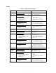

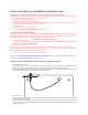
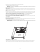
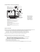

Table Of Contents
- TL260GS / TL265GS
- TL260GS / TL265GS
- Installation Manual
- Limited Warranty
- WARNING
- Note to Installers
- System Failures
- Criminal Knowledge
- Access by Intruders
- Power Failure
- Failure of Replaceable Batteries
- Compromise of Radio Frequency (Wireless) Devices
- Smoke Detectors
- Motion Detectors
- Warning Devices
- Telephone Lines
- Insufficient Time
- Component Failure
- Inadequate Testing
- Security and Insurance
- Warning
- FCC
- Introduction
- 1 . On your hard drive, locate the laptop’s IP address. Retrieve the number of the listening port; this is assigned by the application. You should also have on hand the Communicator’s phone number.
- 2 . Using this phone number send the Communicator an 18-digit SMS text message. This SMS text message is to be configured as: ! + IP address + Port number, without stops or spaces (e.g. !11122233344412345). Note that if you intend to use a port numbe...
- 3 . With an existing installation of DLS IV downloading software on your laptop, you now have the ability to program the Communicator using the GUI on the screen. See Options on page 23 for detailed programming information. Also, please refer to your...
- Models
- Features
- Technical Specifications
- Ratings
- Compatibility
- Table 2: Compatible Receivers and Control Panels
- INSTALLING THE GSM / ETHERNET COMMUNICATOR
- 1 . Wire the telephone line, if available.
- 2 . Wire the PC9155 panel (but not the Communicator).
- 3 . Turn on the PC9155 panel. Program the panel’s telephone number, account code, format, GS / IP module enable, and the communication path priority (i.e. PSTN > Ethernet > GRPS).
- 4 . Turn off the panel.
- 5 . Wire the Communicator through the PC-Link.
- 6 . Proceed to CONNECT 24 Activation Information below.
- 7 . Turn on the panel. Wait for the initialization of the Communicator.
- 1 . Assemble the Communicator
- 2 . Install the Communicator module into the Cabinet
- 3 . Turn on the panel and check signal strength.
- 1 . Attach the Communicator to the inside of the PC9155 control panel cabinet if not already present.
- 2 . Turn on the PC9155 cabinet and check signal strength.
- 1 . Program the hexadecimal digits (DCAA) in the telephone number that will be used to contact the GSM / Ethernet Communicator (panel Options 301, 302, 303, ‘Telephone Phone Number Programming’).
- 2 . In Option 350, program the communication format as SIA FSK.
- 3 . In Options 351 through Option 376, program the call direction sub-options for the phone number being used to communicate using the GSM / Ethernet Communicator.
- 4 . Option 382, sub-option 5 must be set to ON.
- STATUS LEDs
- Trouble Status LED
- Network Connection Status LED
- Signal Strength LEDs
- Table 4: Radio Signal Strength
- 1 . Turn off the power to the Communicator by physically unplugging the unit from its power supply.
- 2 . Attach one end of the extension cable to the Communicator and the other end to the antenna itself.
- 3 . Reattach the power supply and turn on.
- 4 . Move the antenna around until you have received a strong signal.
- 5 . Mount the antenna bracket at that location.
- 1 . Locate the set of five vertically aligned pins in the middle of the Communicator board.
- 2 . Counting from the bottom, the first three pins are reserved for future use. You may discount these.
- 3 . The final two pins require a jumper in order to reset the hardware values.
- 4 . Turn off power to the Communicator.
- 5 . Apply the jumper to the two pins.
- 6 . Turn on power to the Communicator. Wait for ten seconds.
- 7 . Remove the jumper from the pins.
- Table 5: Communicator Troubles on a 9155 Panel
- Table 4: Radio Signal Strength
- Options
- Programming Worksheets

16
NOTE: If a shielded network cable is being used, this step is optional. Nor is it necessary to complete this step if
the cable shield is already grounded by the equipment at the other end.
2. Turn on the PC9155 cabinet and check signal strength.
• Turn on the unit.
• The green LEDs will indicate the signal strength. The right-hand green LED must be On and solid - not flashing - for the loca-
tion to be acceptable. Please refer to STATUS LEDs on page 18 for more information.
TL265GS/GS2065 Communicator Wiring Diagram
Optional Antenna Kits
The PC9155 enclosure contains an internal GSM radio antenna. If the required GSM signal strength cannot be achieved using the
internal GSM antenna, the following selection of GSM extension antenna kits are available to the installer:
• GS15-ANTQ - 4.57m (15’) Internal Antenna Extension Kit (suitable for internal mounting only)
• GS25-ANTQ - 7.62m (25’) External Antenna Extension Kit (suitable for external mounting only)
• GS50-ANTQ - 15.24m (50’) External Antenna Extension Kit (suitable for external mounting only)
Specific instructions for the installation of each extension antenna are included with each kit.
FUSEFUSE
3&%
$17(11
3&%
$17(11$
6,0&DUG
To Remove Connector - insert
small, flat head screwdriver between
cable and Rx/Tx module then gently
pry plug loose. NOTE: Removal with
fingers may damage the connector.
7RDOWHUQDWHH[WHUQDO
DQWHQQDFRQQHFWLRQ
5('
3&/,1.3&/,1.
1(7:25.
TL265GS / GS2065
PC9155
Connecting ethernet cable
to ground may cause
communication problems.
Use with caution.
SHLGND
BATTERY
'*
D G 009077
Network Connection
(Available only for model TL265GS)
Use only CAT5 cable (300ft/100m max.)
Supervised.
PC9155D-433
PC9155G-433
AUDIO/DEFAULT
DSC
UA557
PC-LINK
GNDSHLD
TL265GS / GS2065
T-1R-1 TIP RING IO 2 IO1 -AUX AUX+ AC AC
NOTE: Model PC9155D-433 uses the dual alarm
communicator GSM-GPRS/IP model TL265GS.
Model PC9155G-433 uses the GSM-GPRS only
communicator, model GS2065.
NOTE: For wiring details for the PC9155,
refer to Installation Manual p/n 29007510.
UA558
Radio
SIM Card
Holder
RED
1
Red
Wire
INPUT RATINGS (from PC-Link)
10V - 13.8 VDC
100mA standby
400mA Alarm