
User's Manual
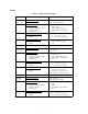

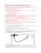
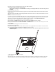
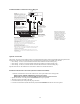

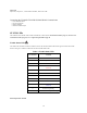
Table Of Contents
- TL260GS / TL265GS
- TL260GS / TL265GS
- Installation Manual
- Limited Warranty
- WARNING
- Note to Installers
- System Failures
- Criminal Knowledge
- Access by Intruders
- Power Failure
- Failure of Replaceable Batteries
- Compromise of Radio Frequency (Wireless) Devices
- Smoke Detectors
- Motion Detectors
- Warning Devices
- Telephone Lines
- Insufficient Time
- Component Failure
- Inadequate Testing
- Security and Insurance
- Warning
- FCC
- Introduction
- 1 . On your hard drive, locate the laptop’s IP address. Retrieve the number of the listening port; this is assigned by the application. You should also have on hand the Communicator’s phone number.
- 2 . Using this phone number send the Communicator an 18-digit SMS text message. This SMS text message is to be configured as: ! + IP address + Port number, without stops or spaces (e.g. !11122233344412345). Note that if you intend to use a port numbe...
- 3 . With an existing installation of DLS IV downloading software on your laptop, you now have the ability to program the Communicator using the GUI on the screen. See Options on page 23 for detailed programming information. Also, please refer to your...
- Models
- Features
- Technical Specifications
- Ratings
- Compatibility
- Table 2: Compatible Receivers and Control Panels
- INSTALLING THE GSM / ETHERNET COMMUNICATOR
- 1 . Wire the telephone line, if available.
- 2 . Wire the PC9155 panel (but not the Communicator).
- 3 . Turn on the PC9155 panel. Program the panel’s telephone number, account code, format, GS / IP module enable, and the communication path priority (i.e. PSTN > Ethernet > GRPS).
- 4 . Turn off the panel.
- 5 . Wire the Communicator through the PC-Link.
- 6 . Proceed to CONNECT 24 Activation Information below.
- 7 . Turn on the panel. Wait for the initialization of the Communicator.
- 1 . Assemble the Communicator
- 2 . Install the Communicator module into the Cabinet
- 3 . Turn on the panel and check signal strength.
- 1 . Attach the Communicator to the inside of the PC9155 control panel cabinet if not already present.
- 2 . Turn on the PC9155 cabinet and check signal strength.
- 1 . Program the hexadecimal digits (DCAA) in the telephone number that will be used to contact the GSM / Ethernet Communicator (panel Options 301, 302, 303, ‘Telephone Phone Number Programming’).
- 2 . In Option 350, program the communication format as SIA FSK.
- 3 . In Options 351 through Option 376, program the call direction sub-options for the phone number being used to communicate using the GSM / Ethernet Communicator.
- 4 . Option 382, sub-option 5 must be set to ON.
- STATUS LEDs
- Trouble Status LED
- Network Connection Status LED
- Signal Strength LEDs
- Table 4: Radio Signal Strength
- 1 . Turn off the power to the Communicator by physically unplugging the unit from its power supply.
- 2 . Attach one end of the extension cable to the Communicator and the other end to the antenna itself.
- 3 . Reattach the power supply and turn on.
- 4 . Move the antenna around until you have received a strong signal.
- 5 . Mount the antenna bracket at that location.
- 1 . Locate the set of five vertically aligned pins in the middle of the Communicator board.
- 2 . Counting from the bottom, the first three pins are reserved for future use. You may discount these.
- 3 . The final two pins require a jumper in order to reset the hardware values.
- 4 . Turn off power to the Communicator.
- 5 . Apply the jumper to the two pins.
- 6 . Turn on power to the Communicator. Wait for ten seconds.
- 7 . Remove the jumper from the pins.
- Table 5: Communicator Troubles on a 9155 Panel
- Table 4: Radio Signal Strength
- Options
- Programming Worksheets

13
INSTALLING THE GSM / ETHERNET COMMUNICATOR
Establishing a communication channel between the Communicator and the PC9155 Panel
Establishing a communication channel between the Communicator and the panel is critical to ensuring the desired operation of the
two units. These steps must be undertaken prior to Connect 24 activation.
1. Wire the telephone line, if available.
2. Wire the PC9155 panel (but not the Communicator).
3. Turn on the PC9155 panel. Program the panel’s telephone number, account code, format, GS / IP module enable, and the
communication path priority (i.e. PSTN > Ethernet > GRPS).
4. Turn off the panel.
5. Wire the Communicator through the PC-Link.
6. Proceed to CONNECT 24 Activation Information below.
CONNECT 24 Activation Information
Only authorized dealers can activate a TL260GS/TL265GS/GS2060/GS2065 Communicator with CONNECT 24. Dealer appli-
cation forms and additional information on the CONNECT 24 Voice Response Unit can be found at the CONNECT 24 web site
www.connect24.com. Please contact CONNECT 24 at the number below for assistance:
USA 1-888-251-7458 CANADA 1-888-955-5583
• First activate your SIM Card.
• Your SIM card must be activated with Connect 24 prior to use. Please call the GS Voice Response Unit (GVRU) at least 24
hours prior to installation at 1-866-910-3865.
• Initialize the Communicator with Connect 24.
Call the GVRU (GS Voice Resonse Unit) at the toll-free number. Follow the voice prompts and enter in your profile number,
installer ID number, installer PIN number and central station number. Ensure all information is available before calling the GVRU.
All this information can be found in your GVRU Activation Package.
7. Turn on the panel. Wait for the initialization of the Communicator.
For installation of the TL260GS/TL265GS/GS2060/GS2065 Communicator, the local installer is responsible for module pro-
gramming. See Compatibility on page 12 for more information.
Installation with PC1616/1832/1864 Control Panel (models TL260GS and GS2060)
1. Assemble the Communicator
• Connect the supplied 12.7cm (5”) antenna cable to the radio by inserting the connector through to the Communicator board
from the back of the bracket, and then pushing the connector firmly into the socket on the Motorola radio.
• Remove the gold nut and the first nylon washer (washer A) from the threaded section on the cable. Insert the threaded section
through and replace the washers and nut. Tighten the assembly by hand.
• Remove the four white plastic standoffs from their bag in the Communicator kit.
• Insert the standoffs in through the back of the supplied bracket, using the four holes provided for that purpose located at each
of the four corners of the bracket.
• Place the bracket on a solid surface. Grasping the edges of the PCB, keeping the board face up, orient the four holes on the
PCB with the four standoffs protruding from the bracket. Push the PCB firmly and evenly onto the standoffs until the PCB is
secured to the bracket.