TL260GS / TL265GS Internet and GSM / GPRS Dual-Path Alarm Communicator GS2060 / GS2065 GSM / GPRS Wireless Alarm Communicator Software Version 1.
Limited Warranty Digital Security Controls warrants the original purchaser that for a period of twelve months from the date of purchase, the product shall be free of defects in materials and workmanship under normal use. During the warranty period, Digital Security Controls shall, at its option, repair or replace any defective product upon return of the product to its factory, at no charge for labour and materials.
Disclaimer of Warranties This warranty contains the entire warranty and shall be in lieu of any and all other warranties, whether expressed or implied (including all implied warranties of merchantability or fitness for a particular purpose) and of all other obligations or liabilities on the part of Digital Security Controls.
WARNING Please Read Carefully Note to Installers This warning contains vital information. As the only individual in contact with system users, it is your responsibility to bring each item in this warning to the attention of the users of this system. System Failures This system has been carefully designed to be as effective as possible. There are circumstances, however, involving fire, burglary, or other types of emergencies where it may not provide protection.
tors, such as when the fire is in a chimney, walls or roofs, or on the other side of closed doors. Smoke detectors may not detect smoke from fires on another level of the residence or building. Every fire is different in the amount of smoke produced and the rate of burning. Smoke detectors cannot sense all types of fires equally well.
Warning The SG-System I is a PLUGGABLE EQUIPMENT TYPE A, using a detachable power supply cord that serves as a disconnecting device. It shall be installed and used in an environment that provides the pollution degree m ax 2 and overvoltages category II, NON-HAZARDOUS LOCATIONS, INDOOR only. The equipment is fixed, wall-mounted and shall be installed as specified in these instructions.
IMPORTANT - READ CAREFULLY: DSC Software purchased with or without Products and Components is copyrighted and is purchased under the following license terms: • This End-User License Agreement (“EULA”) is a legal agreement between You (the company, individual or entity who acquired the Software and any related Hardware) and Digital Security Controls, a division of Tyco Safety Products Canada Ltd.
(b) Separation of Components - The SOFTWARE PRODUCT is licensed as a single product. Its component parts may not be separated for use on more than one HARDWARE unit. (c) Single INTEGRATED PRODUCT - If You acquired this SOFTWARE with HARDWARE, then the SOFTWARE PRODUCT is licensed with the HARDWARE as a single integrated product. In this case, the SOFTWARE PRODUCT may only be used with the HARDWARE as set forth in this EULA. (d) Rental - You may not rent, lease or lend the SOFTWARE PRODUCT.
WARRANTY, NOR TO ASSUME FOR IT ANY OTHER WARRANTY OR LIABILITY CONCERNING THIS SOFTWARE PRODUCT. (m) EXCLUSIVE REMEDY AND LIMITATION OF WARRANTY UNDER NO CIRCUMSTANCES SHALL DSC BE LIABLE FOR ANY SPECIAL, INCIDENTAL, CONSEQUENTIAL OR INDIRECT DAMAGES BASED UPON BREACH OF WARRANTY, BREACH OF CONTRACT, NEGLIGENCE, STRICT LIABILITY, OR ANY OTHER LEGAL THEORY.
Introduction The GS2060/GS2065 Communicator is a GSM / GPRS wireless alarm communicators that send alarm system information to a System I, System II, or System III receiver through the GSM / GPRS digital cellular network. The TL206GS/TL265GS Communicators are dual-path alarm communicators that send alarm system information to a System I, System II, or System III receiver through the Ethernet / Internet or the GSM / GPRS digital cellular network.
• • • • • • • • • • Supervision heartbeats via GSM/GPRS and Internet 128-bit AES encryption via GSM/GPRS and Internet Full event reporting SIA format PC-Link connection Signal strength and Trouble display Installer Code (International version only) Activating and initializing through Connect 24 Advanced remote and local programming via DSC DLS IV Quad-Band: 850 MHz, 1900 MHz, 900 MHz and 1800 MHz Technical Specifications The input voltage to the TL260GS/TL265GS/GS2060/GS2065 Communicator can be drawn from
Ratings Table 1: Communicator Ratings Model TL260GS (Ethernet & GSM) TL265GS (Ethernet & GSM) Category Values 10V ~ 13.
Table 1: Communicator Ratings Model Category Values Mechanical Specifications • Enclosure Dimensions • Weight GS2065 (GSM only) • 101mm x 149mm x 18mm • 320g Power Supply Ratings • Input Voltage • Current 10V ~ 13.
INSTALLING THE GSM / ETHERNET COMMUNICATOR Establishing a communication channel between the Communicator and the PC9155 Panel Establishing a communication channel between the Communicator and the panel is critical to ensuring the desired operation of the two units. These steps must be undertaken prior to Connect 24 activation. 1. Wire the telephone line, if available. 2. Wire the PC9155 panel (but not the Communicator). 3. Turn on the PC9155 panel.
• Insert the previously activated SIM card face down in the SIM card holder. 2. Install the Communicator module into the Cabinet NOTE: Before installing the TL260GS/GS2060 or inserting or removing the SIM card, ensure that the system is turned off. • Remove the cabinet’s front cover. • Remove the circular knockout located in the top-right section of the panel. This knockout will be used for connection of the supplied antenna. • Attach the 4-pin PC-Link cable connector to the panel board.
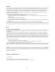
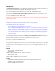
TL260GS/GS2060 Communicator Wiring Diagram To external antenna Radio AUDIO/DEFAULT DSC SIM Card Holder UA557 WARNING! All connections to the TL260GS/GS2060 module are power limited. Do not route any wiring over the circuit boards. Maintain at least 1” (25.4mm) separation between circuit board and wiring. A minimum of 1/4” (7mm) separation must be maintained at all points between non-power limited wiring and power limited wiring.
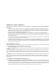
NOTE: If a shielded network cable is being used, this step is optional. Nor is it necessary to complete this step if the cable shield is already grounded by the equipment at the other end. 3&% 3&% $17(11 $17(11$ 6,0 &DUG FUSE 7R DOWHUQDWH H[WHUQDO DQWHQQD FRQQHFWLRQ To Remove Connector - insert small, flat head screwdriver between cable and Rx/Tx module then gently pry plug loose. NOTE: Removal with fingers may damage the connector. 3& /,1. PC9155 5(' 1(7:25.
PC1616 / PC1832 / PC1864 Programming In order that your Communicator and your panel operate correctly together, specific panel options must be set. Take the following steps to ensure that your Communicator and your panel work together as intended. These options must be set at the panel keypad. 1. Program the hexadecimal digits (DCAA) in the telephone number that will be used to contact the GSM / Ethernet Communicator (panel Options 301, 302, 303, ‘Telephone Phone Number Programming’).
Option 382 Option 382, sub-option 5, ‘T-Link Interface Enabled’, must be set to On. Connecting the TL260GS/TL265GS/GS2060/GS2065 Communicator • • • • Power Terminal Blocks PC-Link Connection Ethernet Interface Hardware Default Jumper STATUS LEDs The module has four onboard surface mount LED indicators. These include a Trouble Status LED on page 18, a Network Connection Status LED on page 20, and two Signal Strength LEDs on page 20.
This trouble will be indicated when communication between the Communicator module and the control panel fails. If for some reason the the module can not communicate with the panel - eg, loss of power to the panel - the module itself will send a ‘Panel Absent Trouble Event’ message to the central station receiver. When communication returns, a ‘Panel Absent Restore Event’ is sent by the module to the central station receiver. Its reporting codes are ET0001 for Trouble, ER0001 for Restore.
Network Connection Status LED The normal state of the Red Network Connection Status LED is Off when there are no network connection issues present. This LED will activate when there is an issue with either the Ethernet or the GPRS network connection.
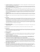
AUDIO/DEFAULT UA557 DG009054 DSC 5. Apply the jumper to the two pins. 6. Turn on power to the Communicator. Wait for ten seconds. 7. Remove the jumper from the pins. The hardware settings of your Communicator have now been reset to their default values. PC-LINK Communicator Troubles on a 9155 Panel The following troubles will appear on the keypad LCD when encountered by a Communicator on the 9155 panel.
Table 5: Communicator Troubles on a 9155 Panel Trouble Condition Loss of Time and Date Description If power was lost completely (AC and battery), the time and date will need to be re-programmed. Press *. User Action Re-program Time and Date Communicator Troubles on a 1616 / 1832 / 1864 Panel The General System trouble is the sole trouble that will appear on the keypad LCD when encountered by a Communicator on the 1616 / 1832 / 1864 panel.
Options System Options GPRS Receiver 1 Options Option 001: Ethernet IP Address on page 23 Option 002: Ethernet IP Subnet Mask on page 23 Option 003: Ethernet Gateway IP Address on page 23 Option 004: Receiver Supervision Interval on page 24 Option 005: System Toggle Options on page 24 Option 201: GPRS Receiver 1 Account Code on page 27 Option 202: GPRS Receiver 1 DNIS on page 27 Option 203: GPRS Receiver 1 Address on page 27 Option 204: GPRS Receiver 1 Port on page 27 Option 205: GPRS Receiver 1 APN on
Enter the Ethernet Gateway IP address of the dual communicator. The address must be entered as a dotted decimal number (e.g. 192.168.1.100). Each three-digit segment of the address must be within a valid range of 000 to 255. The gateway is used in the event that the destination address is not on the local network. The data will need to be sent through a router device. This is the address of that router device.
Table 7: System Toggle Options Valid Data Range Effect Default Bit 8 Reserved Disabled (Off) NOTE: *Receivers 1 and 3 can be supervised; if enabled, heartbeats are sent. Receivers 2 and 4 cannot be supervised. Programming Options Option 011: Installer Code Default (CAFE) This option is used to program the installer code of the Communicator module. Valid entries range from 0000 to FFFF hexadecimal.
address must be entered as four 3-digit entries (e.g. 192.168.1.101). Each 3-digit segment of the address must be within a valid range of 000 to 255. Option 104: Ethernet Receiver 1 Local Port Default (3060) You can use this option to set the value of the local outgoing port. You can set the value of this port in case your installation is located behind a firewall and must be assigned a particular port number as determined by your network administrator. Valid entries range from 0000 to FFFF hexadecimal.
GPRS Receiver 1 Options Option 201: GPRS Receiver 1 Account Code Default (0000000000) The account code is used by the central station to distinguish between transmitters. This account code is used when transmitting signals to the central station receiver. Signals received from the control panel will use the control panel account number. Valid entries will range from 0000000000 to FFFFFFFFFF hexadecimal.
Option 213: GPRS Receiver 2 Address Default (0.0.0.0) Enter the GPRS receiver 2 IP address. This information will be provided by your central station. Note that when a valid address has been entered, the GPRS will be considered to be enabled and will communicate events over the GPRS channel. The address must be entered as four 3-digit entries (e.g. 192.168.1.101). Each 3-digit segment of the address must be within a valid range of 000 to 255.
You can use this option to confirm the IP address of the Ethernet port. Option 993: GPRS IP Address You can use this option to confirm the IP address of the GPRS connection. Option 994: SIM Number You can use this option to confirm the SIM number of the device. Option 995: Telephone Number You can use this option to confirm the telephone number of the device. Option 996: IMEI Number You can use this option to confirm the IMEI of the radio.
Bit 6 - Remote Firmware Upgrade Bit 7 - UL Remote Firmware Upgrade Bit 8 - Reserved |______| |______| |______| Programming Options Option 011: Installer Code |_____|_____|_____|_____| Option 012: DLS Port |_____|_____|_____|_____| Option 013: DLS Local Port |_____|_____|_____|_____| Ethernet Receiver 1 Options Option 101: Ethernet Receiver 1 Account Code |_____|_____|_____|_____|_____|_____|_____|_____|_____|_____| Option 102: Ethernet Receiver 1 DNIS Option 103: Ethernet Receiver 1 Address |____
Option 213: GPRS Receiver 2 Address |____|____|____|____|____|____|____|____|____|____|____|____| Option 214: GPRS Receiver 2 Port |_____|_____|_____|_____| Option 215: GPRS Receiver 2 APN |_____|_____|_____|_____| GPRS Options Option 221: GPRS Public APN _______________________________________________________ Option 222: GPRS Login User Name _______________________________________________________ Option 223: GPRS Login Password _______________________________________________________ System Info
Technical Support: 1-800-387-3630 (Canada / US) 905-760-3000 (International) www.dsc.