
User's Manual


10
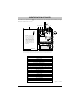
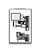
Fig. 3 - Telephone Connection
GS3060 WIRING DIAGRAMS
DSC RM-2 Relay
NC
C
NO
Auxiliary
Power Supply
(Optional)
(used to power the
GS3060 Radio)
+
1
2
V
D
C
GND
Control
Panel
EOL
Resistor
See Note 3
ZONE
TERMINALS
(See Note 1)
- +
+
1
2
V
D
C
G
N
D
CONTROL PANEL
Aux Power
+ -
Supervision
Relay
See Note 2
19
18
17
1614
20
15
12
1110
97
13
8
6
GS3060
RED (R)
GREEN (T)
GRAY (R)
BROWN (T)
RJ-31X
RING
TIP
CONTROL PANEL
Incoming
Phone line
Handset
RI
TI
TI
RI
TIP
RING
4
321
5
GS3060
TIP T1 R1
RNG
COM
12 34
AUX+
PGM
TAMPER COM Z1 Z2 Z3 Z4
+ 12V -
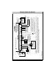
NOTES:
1. Program the Control Panel’s input
Zone/Point as 24h “Supervisory” type
with the keypad only annunciation
when activated.
2. A supervision relay, DSC model
RM-2 can be used, as indicated in
Fig. 4 in order to provide supervision
of the control panel (for total power
loss) when the GS3060 is powered
by a Separate Power Supply.
When the GS3060 is powered by the
control panel the relay is not required
since a loss of voltage at the power
input terminals on the GS3060 will
generate a trouble signal transmission
to the monitoring station.
3. Output 4 on the GS3060 must be
set as “Active High”.
Fig. 4 - Optional Power Supply And Supervision Wiring Diagram