
User's Manual


7
Contact ID (Voice) Mode
This operating mode allows the GS3060 to send calls to the Central Station through the GSM voice
channel. When active, the GS3060 will transfer the phone number dialed by the panel to the GSM
network and connect with the land line receiver through the GSM voice channel.
The Z1 - Z4 alarms and other event codes can be generated in Contact ID format and transmitted to
a standard PSTN line card. Event Codes and Customer Account Codes must be programmed to
transmit event signals.
The GS3060 will call all programmed telephone numbers for each event (four telephone numbers
maximum of up to 20 digits (digits and + signs). The GS3060 will make three attempts for each
telephone number then quit if unsuccessful. If programmed, the PTM numbers will also be used as
filters. Voice calls are restricted to the phone numbers in the PTM table.
NOTE: The GS3060 default on-line time limit is 3 minutes.
NOTE: The GS3060 has been verified against major manufacturers for CONTACT ID, 10 bps
and 20 bps protocols and, in places with optimum GSM signal reception, SIA format. However,
since the GS3060 unit is only acting as a bridge, good performance will be determined by the
alarm panel connected to the GS3060. Communication tests must be performed.
Inputs
The GS3060 has 4 inputs that can be used to trigger specific communications. These events will
transmit using Contact ID format with Inputs 1-4 reporting as [991] to [994] respectively. Default
settings are:
INPUT 1- FIRE INPUT 3 - BURGLARY
INPUT 2 - PANIC ALARM INPUT 4 - SYSTEM TROUBLE
These inputs are normally open and will activate when a short condition is detected between the
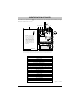
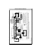
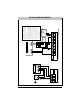
terminal and the COM. Refer to the GS3060 Wiring Diagram (Figure 2) at the back of this manual.
NOTE: These inputs communicate using Contact ID format.
NOTE: For UL/ULC installations, connections between alarm panel outputs and GS3060 inputs
shall be run in mechanical protective conduits. To reduce interference with the antenna, it is
recommended that the metal conduit is not connected to the knock-outs on the top of the cabinet.
Outputs
The GS3060 has 4 programmable outputs to activate in response to the associated events. Refer to
the GS3060 Wiring Diagram (Figure 2) at the back of this manual.
Activating the Outputs
The GS3060 has 4 open collector outputs capable of a maximum of 50mA. Internal events on the
GS3060 can trigger the outputs to turn on an LED or activate an input on the host panel. The default
settings are as follows:
OUTPUT 1 - Land Line TOUTPUT 1 - Land Line T
OUTPUT 1 - Land Line TOUTPUT 1 - Land Line T
OUTPUT 1 - Land Line T
rr
rr
r
oubleouble
oubleouble
ouble
Output is normally high and will switch to ground when the telephone line is down.
OUTPUT 2 - GSM Model or Network TOUTPUT 2 - GSM Model or Network T
OUTPUT 2 - GSM Model or Network TOUTPUT 2 - GSM Model or Network T
OUTPUT 2 - GSM Model or Network T
rr
rr
r
oubleouble
oubleouble
ouble
Output is normally high and will switch to ground when the GS3060 can’t connect or communicate
to the GSM network.
OUTPUT 3 - Power Supply or BatterOUTPUT 3 - Power Supply or Batter
OUTPUT 3 - Power Supply or BatterOUTPUT 3 - Power Supply or Batter
OUTPUT 3 - Power Supply or Batter
y Ty T
y Ty T
y T
rr
rr
r
oubleouble
oubleouble
ouble
Output is normally high and will switch to ground when there is a problem with the power source.
OUTPUT 4 - General Module TOUTPUT 4 - General Module T
OUTPUT 4 - General Module TOUTPUT 4 - General Module T
OUTPUT 4 - General Module T
rr
rr
r
oubleouble
oubleouble
ouble
Output is normally low and will switch to high when a GSM Trouble, Power Supply/Battery Trouble
and/or a Failure to Communicate (FTC) trouble is detected.
NOTE: Once an output has been activated automatically, it will not restore its state until all
the causes of activation are cleared.