GS3060 v3.1 GSM-GPRS INTERFACE INSTALLATION MANUAL WARNING: This manual contains information on limitations regarding product use and function and information on the limitations as to liability of the manufacturer.
Table of Contents INTRODUCTION ................................................................................ 1 Features ........................................................................................ 1 Technical Specifications ................................................................ 1 Ratings .......................................................................................... 1 Description ....................................................................................
FCC COMPLIANCE STATEMENT CAUTION: Changes or modifications not expressly approved by Digital Security Controls could void your authority to use this equipment. This equipment generates and uses radio frequency energy and if not installed and used properly, in strict accordance with the manufacturer's instructions, may cause interference to radio and television reception.
INTRODUCTION The GS3060 is a backup wireless communicator that sends alarm system information to a System III or System II receiver through a GSM/GPRS wireless network or to a standard land-line receiver through the GSM voice channel. For use with listed compatible control units as indicated in the control unit manufacturer's installation instructions.
This equipment GS3060 is fixed and shall be installed by Service Persons only (Service Person is defined as a person having the appropriate technical training and experience necessary to be aware of hazards to which that person may be exposed in performing a task and of measures to minimize the risks to that person or other persons). It shall be installed and used within an environment that provides the pollution degree max 2, over voltages category II, in non-hazardous, indoor locations only.
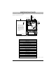
IDENTIFICATION OF PARTS The numbers in square brackets [ ] in this manual refer to the main parts of the GS3060 (see Fig.1 below) described in this section. 2 1 15 18 5 4 17 3 6 4 LOCK JP3 OPEN OFF ON 6 1 JP3 5 9 NOTE: For UL/ULC Installations, connections between the alarm control panel outputs (telephone interface Tip/Ring or output relay contacts) and GS3060 inputs (Tip/Ring, Z1-Z4) shall be run in mechanical protective conduit within 20ft and in the same room.
INSTALLING THE GS3060 CONNECT 24 Enrollment Information Only authorized dealers can enroll a GS3060 with CONNECT 24. Dealer application forms and additional information on the CONNECT 24 Voice Response Unit can be found at the CONNECT 24 w.connect24.com .connect24.com. Please contact CONNECT 24 at the number below for assistance: www web site ww CANADA 1-888-955-5583 USA 1-888-251-7458 NOTE: Steps 1 and 2 should be completed before powering the GS3060 unit.
PGM1 (7), PGM2 (8), PGM3 (9), PGM4 (10) Pr Programmable ogrammable open-collector outputs These outputs can be activated by programmed events, refer to “Activating the Outputs” for details. The maximum current sink of each output must not exceed 50mA. AUX+ (11) Auxiliar y 12V Output Auxiliary om the +12V Output, 200mA PTC Protected. NOTE: Cur Currrent drawn fr from terminal directly from om this ter minal is dir ectly fr power supply determining supply..
OPERATING PRINCIPLES Simulated Land Line Mode The simulated land line provides the alarm control panel (with dialer interface) with a backup line TIP/RNG TIP/RNG) drops below in the event of PSTN line trouble. If the voltage on the land line terminals (TIP/RNG 4V for a period of between 10 to 45 seconds (depending on the device connected to the T1/R1 terminals), the GS3060 will switch the connected telephone device to the GSM Network for approximately 30 to 40 seconds.
Contact ID (Voice) Mode This operating mode allows the GS3060 to send calls to the Central Station through the GSM voice channel. When active, the GS3060 will transfer the phone number dialed by the panel to the GSM network and connect with the land line receiver through the GSM voice channel. The Z1 - Z4 alarms and other event codes can be generated in Contact ID format and transmitted to a standard PSTN line card. Event Codes and Customer Account Codes must be programmed to transmit event signals.
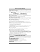
Contact ID Events Description Event Codes INPUT 1 ACTIVATION: ............................................................................... E110 FIRE ZONE 001 991 INPUT 1 RESTORAL: ................................................................................ R110 FIRE ZONE 001 991 INPUT 2 ACTIVATION: .............................................................. E120 PANIC ALARM ZONE 002 992 INPUT 2 RESTORAL: ................................................................
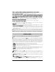
GROUND CONNECTION RJ-45 Earth-ground Ground wire from building electrical installation 2 LE 3 9 R I N G optional use of PGM output (See Programming) Connect relay contacts to a zone input on the alarm control panel for GS3060 troubles supervision (24h type zone) RM-1 Relay 1K5 Fig. 2 - Wiring Diagram WARNING: Incorrect connections may result in PTC failure or improper operation.
BROWN (T) GRAY (R) TI GREEN (T) 10 RI RED (R) RING TIP TIP RNG T1 R1 GS3060 TI 6 7 COM 1 (used to power the GS3060 Radio) Auxiliary Power Supply (Optional) 4 AUX+ TAMPER COM Z1 Z2 Z3 Z4 + 12V - 9 10 11 12 13 14 15 16 17 18 19 20 PGM 2 3 8 Supervision Relay See Note 2 3. Output 4 on the GS3060 must be set as “Active High”.
©2007 Digital Security Controls Printed in Canada 2 9 0 0 7 4 6 3 R0 0 1