
User's Manual


4
GS3055-I
Description
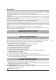
This Device provides total confidence in all security and surveillance applications. It manages SMS and Central Station
transmissions and can simulate the land line in the event of trouble (land line down) or even substitute the land line completely
in areas where the GSM service is provided and where the land line is not available.
This Device supports CONTACTID, 10 bps and 20 bps protocols and, in places with optimum GSM signal reception, SIA and
CESA protocols.
The GS3055-I has the added capability of communicating alarm signals via the GPRS data network. The capability enables
a fast reliable path to central stations equipped with a Sur-Gard System III, System II receiver, or with the PC based WinBCS
software (version 2.0 or higher).
By connecting a GS3055-I to a control panel's standard PSTN interface, telephone based Contact ID signals are decoded and
seamlessly routed through the GPRS network to any of the compatible receiver options.
The performance of this Device depends greatly on GSM Network coverage, therefore, it should not be mounted without first
performing placement tests to determine the best location (best reception). This Device has 4 Input lines which can be used to
activate SMS and/or Contact ID transmissions (Trouble alert, Periodic messages or Pay-As-You-Go Balance (for pre-paid SIM
Cards).
This Device has 4 Outputs which can be set up from remote locations or used for status signalling.
Due to the characteristics of GSM Networks, this Device can activate only as intended and cannot be used as a modem for
fax/data transmissions or for teleservice operations.
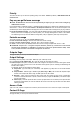
IDENTIFICATION OF PARTS
The numbers in square brackets [ ] in this manual refer to the main parts of the GS3055-I (see Fig. 1) described in this section.
INSTALLING THE DEVICE
This device shall be installed by qualified SERVICE PERSONS only. This device must be installed indoors in a non-
hazardous location. This Device should be located in a dry place away from radio transmitters and similar devices.
,,
,,
,
Test the GSM Network reception before mounting this Device in the proposed placement.
1. Remove the 4 screws and the metal casing [1].
2. Using the back box, mark the 4 screw locations then drill the anchor screw holes.
Check for cable conduits and water pipes before drilling.
3. Using anchor screws (not included), mount the back box to the wall.
4. Lay the cables, then pull them through the cable entry [14].
5. Fit the antenna [2] (ensure that the bolt [3] is fastened tightly).
6. Using the connector [5], connect the GSM Module [17].
7. Following the arrow on the board, insert the SIM-CARD [6] face down in the SIM holder (see Figure 1).
The SIM-CARD PIN must be disabled.
8. Complete the connections on the terminal board [12].
9. Using the 4 scews and washers, reattach the frontplate [1] securely to the back box.
,,
,,
,
Connect power and TNV circuit only after the cabinet has been secured to the building or structure and has
been connected to the protective earth ground.
CONNECTING THE DEVICE
This section describes the various terminals. Fig. 2 shows a typical wiring diagram.
(1) Earth: This terminal must be connected to the Mains Earth, in order to comply with the Telecommunications Network
Safety Standards (Overvoltage Protection Requirements).
LE (2-3) External telephone line: These terminals can be connected to the land line.
LI (4-5) Internal telephone line: These terminals (normally connected to the land line) must be connected to the telephone
device terminals (for example, terminals L.E.).
(6-14) Negative: Power Supply.