
User's Manual
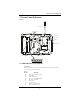
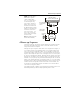
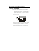
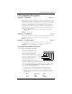
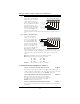

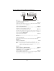

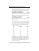
Table Of Contents
- Table of Contents
- 1 Introduction
- 2 Installation, Testing & Factory Defaults
- 3 Controls and Indicators
- 4 Power up Sequence
- 5 System Programming
- 6 Programming Descriptions
- 7 Programming Worksheets
- Glossary of Terms
- Skyroute CL3050 Quick Start:
- Note: Before you start, you must be enrolled with CONNECT 24 as an authorized installer to activa...
- STEP 1 - SELECT BEST LOCATION (See Section 2.1)
- Connect the Skyroute transceiver to a 7 Ah battery, as described in Section 2.1. Determine the be...
- STEP 2 - CONNECT NECESSARY WIRING (See Section 6)
- Mount the Skyroute, determine the desired mode of operation and connect the appropriate control p...
- STEP 3 - PROGRAM (See Section 5)
- If the default programming must be changed, connect a PowerSeries keypad as shown in Section 5 an...
- STEP 4 - ACTIVATE (See Section 2.1)
- Call the Connect 24 Voice Response Unit (VRU) at the toll free number provided with your Dealer C...
- STEP 5 - TEST (See Section 2.2)
- Once activated, send two signals to your central station to confirm proper operation.
- YOUR SKYROUTE INSTALLATION IS NOW COMPLETE.
- ALL OTHER PROGRAMMING SECTIONS IN THIS MANUAL ARE OPTIONAL.
- Appendix A: Reporting Codes

Skyroute CL3050 Standalone Wireless Communicator
10
[02] Mode 2 - (2) 24-Hour Zones
In this mode, both the YEL and
GRN terminals on the Skyroute
CL3050 will be used as zone
inputs. These zones will support
the DSC standard EOL configura-
tion and loop response. Pro-
gramming sections will allow the
installer to change the default
zone types and attributes. The
Skyroute CL3050 will continu-
ously monitor these zones and transmit any alarms that occur to the central sta-
tion.
[03] Mode 3 - (8) 24-Hour Zones
In this mode, the Skyroute
CL3050 is connected to a
PC5108 zone expander using
the corresponding RED, BLK,
YEL and GRN terminals. The
Skyroute CL3050 will drive the
Keybus to communicate with
the PC5108. A +12V
DC
sup-
ply connected to the RED and
BLK terminals is required
when using this mode. The Programming sections will allow the installer to
change the default zone types and attributes. The Skyroute CL3050 will continu-
ously monitor these zones and transmit any alarms that occur to the central
station.
Note:
This configuration can not be used with an AC supply.
Note:
Jumpers on the PC5108 must be set as follows:
J1
J2
J3
ON
OFF
ON
J4
J5
J6
OFF
OFF
ON
Default -
[01 -03] dependant on start up configuration
[11] Skyroute CL3050 Configuration Options 1
Option 1 - A Channel Selected/ B Channel Selected.
All Modes
This Option determines whether cellular channel
“B”
or channel
“A”
is used
. In
Canada, Channel B is used (Default). In the USA refer to the SID list for the chan-
nel of the cellular service provider in your area.
Default -
Channel B
Option 2 - Normally Closed Loops/ End-of-line Resistors
Mode 2, 3
Normally Closed Loops can be wired as shown. Multiple
Normally Closed contacts can be wired in series. For Double
or Single EOL resistors this option must be set to
OFF
.
Default -
Normally Closed (N/C) Loops.
Option 3 - Double EOL Resistors/Single EOL Resistors
Mode 2, 3
This option selects Double EOL resistors (ON) or Single EOL resistors (OFF) wired
as indicated
Input Voltage
9-12V or V
AC DC
Zone 1 Input
Zone 2 Input
Zone Common
Trouble Output
RED BLK YEL GRN COM PGM
To Keybus
Connections
on PC5108
System Common
Trouble Output
RED BLK YEL GRN COM PGM