
User's Manual
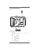
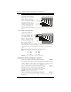


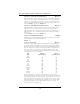
Table Of Contents
- Table of Contents
- 1 Introduction
- 2 Installation, Testing & Factory Defaults
- 3 Controls and Indicators
- 4 Power up Sequence
- 5 System Programming
- 6 Programming Descriptions
- 7 Programming Worksheets
- Glossary of Terms
- Skyroute CL3050 Quick Start:
- Note: Before you start, you must be enrolled with CONNECT 24 as an authorized installer to activa...
- STEP 1 - SELECT BEST LOCATION (See Section 2.1)
- Connect the Skyroute transceiver to a 7 Ah battery, as described in Section 2.1. Determine the be...
- STEP 2 - CONNECT NECESSARY WIRING (See Section 6)
- Mount the Skyroute, determine the desired mode of operation and connect the appropriate control p...
- STEP 3 - PROGRAM (See Section 5)
- If the default programming must be changed, connect a PowerSeries keypad as shown in Section 5 an...
- STEP 4 - ACTIVATE (See Section 2.1)
- Call the Connect 24 Voice Response Unit (VRU) at the toll free number provided with your Dealer C...
- STEP 5 - TEST (See Section 2.2)
- Once activated, send two signals to your central station to confirm proper operation.
- YOUR SKYROUTE INSTALLATION IS NOW COMPLETE.
- ALL OTHER PROGRAMMING SECTIONS IN THIS MANUAL ARE OPTIONAL.
- Appendix A: Reporting Codes

3 Controls and Indicators
5
3 Controls and Indicators
Figure 2
3.1 LED Indicators (see figure 2)
Yellow LED
During normal operation, the yellow LED will indicate the system status with a
series of flashes as indicated below.
No. of
Flashes Indication
1
2
3
4
5
6
7
8
9
No trouble conditions present
Low battery
Input supply failure
Not enrolled at
Connect 24
No service available*
Radio failure
PC5108 failure
Failure to communicate
Zone tamper/fault trouble
Enroll Button
Battery (6 V )
DC
Green LED
Yell ow LE D
Red LED
Ta mper Sw i tc h
Mounting Holes
Wire Access
Antenna