
Installation Manual


4
2.4 Mount and Wire the LINKS2450
1. Run the panel wiring and the power supply wiring to the LINKS2450 mounting
location.
2. Remove the four screws that attach the LINKS2450 circuit board to the
plastic cabinet.
3. Pull all wires through the hole at the back of the cabinet.
4. Mount the cabinet securely to the wall. Use the appropriate wall anchors
when securing the panel to drywall, plaster, concrete, brick or similar
surfaces.
5. Reattach the LINKS2450 into the mounted cabinet using the four mounting
screws.
6. Find the antenna connection in the hole at the top of the cabinet. Secure the
antenna to the LINKS2450 antenna connector.
NOTE: Make sure an antenna is always connected to the LINKS2450 whenever it
is operated. The unit will not work and may be damaged if an antenna is not in-
stalled.
7. Complete all wiring: If you will be connecting the LINKS2450 to a PC5015,
PC5010, PC1575/1580, PC1555/1565 or PC580/585 panel, go to step 8a. If
you will be connecting the LINKS2450 to a PC4010 or PC4020 panel, go to
step 8b.
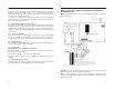
8a. Connect the LINKS2450 according to diagram 2-2. Make sure jumper J3
on the LINKS2450 is NOT shorted.
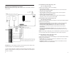
8b. Connect the LINKS2450 to a PC2550RK keypad according to diagram 3-
1. Make sure jumper J3 on the LINKS2450 IS SHORTED. When you have
finished programming, disconnect the power supply and the PC2550RK
keypad from the LINKS2450.
Remove the short from jumper J3
. Connect
the LINKS2450 to the control panel according to diagram 2-3.
NOTE: Double-check all wiring to ensure that it is correct. Incorrect wiring connec-
tions may cause the LINKS2450 to operate improperly, or may damage the unit.
8. Connect the power: Connect the power terminals (VTX
+
and VTX
–
) to a 11.5 -
14V
DC, 1A power supply.
CAUTION: Do not connect the power supply until all other wiring, including the
antenna connection, has been completed and checked to ensure that it is correct.
13
RESET LINKS2450 PROGRAMMING TO FACTORY
DEFAULT
Section 6
If you need to reset the LINKS2450 to factory default programming, follow the
directions in the appropriate sections below.
6.1 Reset the LINKS2450 on a PC1575/1580 Panel
To reset the LINKS2450 on a PC1575/1580 panel, enter [96] [Installer’s Code] [96].
6.2 Reset the LINKS2450 on a PC5015 v2.2, PC5010 v2.0, PC1555/
1565 or PC580/585 Panel
To reset the LINKS2450 on a PC5015 v2.2, PC5010 v2.0 or PC1555/1565 panel,
enter [993] [Installer’s Code] [993].
NOTE: This command is unavailable on PC5010 v1.0. If v1.0 is used, you must
perform a hardware reset (see section 6.3 below).
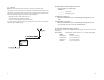
6.3 Perform a Hardware Reset (All panels)
To reset the LINKS2450 when connected to a PC5010 v1.0 or a PC4010/4020
panel, you must perform a hardware reset. To do this:
1. Remove all power from the LINKS2450
2. Short j umper J3
3. Remove all wires from the YEL and GRN terminals
4. With a piece of wire, short the YEL terminal to the GRN terminal
5. Apply power to the LINKS2450 for 5 seconds.
6. Remove power from the LINKS2450
7. Reconnect all original wiring and re-power the LINKS2450
NOTE: If the LINKS2450 is connected to a PC4010/4020 panel, the programming
done in the panel software will not be reset. See section 3.2, step 5 for information
on re-programming the PC4010/4020 sections.