
Installation Manual


3
INSTALLING THE LINKS2450
Section 2
Before installing the LINKS2450, install and test the security system to which it will
be connected, according to the system’s Installation Manual.
2.1 Unpacking the LINKS2450
Check that each of these parts is included in your LINKS2450 package.
• LINKS2450 circuit board
• LINKS2450 plastic cabinet
CAUTION: Due to the sensitivity of the RF circuitry, avoid any contact with the coils
and potentiometers on the LINKS2450 circuit board.
2.2 Select a Mounting Location
The area where you mount the LINKS2450 should be:
• dry
• close to the installed alarm control panel cabinet.
• far from sources of interference, including: electrical noise such as computers,
televisions and electric motors in appliances and heating and air conditioning
units; large metal objects like heating ducts and plumbing which may shield the
antenna. If you must mount the LINKS2450 near such items, you may have to
mount the antenna on a remote bracket away from the LINKS2450.
• close to the power supply. See section 2.3 “Connect a Power Supply”.
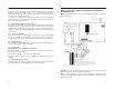
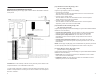
2.3 Connect a Power Supply
You can use the Bell+ and Aux- terminals from the control panel to power the
LINKS2450. If you will be using a separate power supply, install it near the
LINKS2450. Refer to the power supply’s installation instructions, for more information.
NOTE: The current drawn by the LINKS2450 and the siren(s) connected to the Bell
terminals must not exceed that specified by the rating of the control panel. Refer to
your control panel’s Intallation Manual for more information.
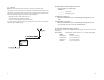
The wiring between the LINKS2450 and the power supply should not be longer than
indicated in the table below:
Wire Gauge (AWG) Maximum Wire Length (feet / meters)
22 15' / 4.5m
20 25' / 7.5m
18 40' / 12.0m
You can double the maximum wire length if you double the conductors and connect
them in parallel. Mount the LINKS2450 as close to the power supply as possible.
14
PROGRAMMING WORKSHEETS
[01] Module Configuration
Default Option ON OFF
ON I_______I
1
Communications Communications
enabled disabled
OFF
I_______I
2
Serial connection Keybus connection
[10] LINKS2450 Account Code
Default
FF FF I_______I_______I l_______I_______I Valid entries are 00-FF
Enter two 2-digit hexadecimal numbers.
[20] Maintenance Alarms and Restoral Reporting Codes
Default
= FF
I_______I_______I Keybus/Serial Fault Alarm
I_______I_______I Keybus/Serial Fault Restoral
I_______I_______I For future use
[30] Call Direction Options (PC5015, PC5010, PC1575/1580
and PC1555/1565 panels only)
Default Option ON OFF
ON
I_______I
1
Alarm/restore reporting enabled Disabled
ON
I_______I
2
Tamper/restore reporting enabled Disabled
OFF
I_______I
3
Opening/closing reporting enabled Disabled
ON
I_______I
4
System maintenance reporting enabled Disabled
ON
I_______I
5
System test transmission reporting Disabled
enabled
OFF
I_______I
6-7
For future use Enabled
OFF
I_______I
8
Future event Support Disabled
[81] Miscellaneous Alarm Reporting Codes (PC1575/1580 panel only)
Default
= FF
I_______I_______I General Zone Fault Alarm
I_______I_______I General System Tamper Alarm
I_______I_______I General System Supervisory Alarm
[82] Miscellaneous Restoral Reporting Codes
(PC1575/1580 panel only)
Default
= FF
I_______I_______I General Zone Fault Restore
I_______I_______I General System Tamper Restore
I_______I_______I General System Supervisory Restore