
Installation manual

XR6/XR3 Installation Manual Control and monitoring
Issue 3.0 2009-07-15 Page 9-1
Section 9: Control and monitoring
This section describes control and monitoring of the XR6/XR3 transmitter. This section includes the
following topics:
• Controls
• Alarm definitions
• Remote control circuits and alarms - see page 9-7
• Remote performance monitoring - see page 9-12
• LAN interface (NxLink) - see page 9-13
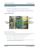
Controls
The XR6/XR3’s graphic user interface (GUI) lets you control a number of transmitter functions and
set parameters and schedules. (For detailed information about the GUI, refer to the XR6/XR3
Operating and Maintenance Manual.) In addition, you can control the on/off status, the active (A/B)
exciter, the preset RF power level, the power level adjustment, and system alarm reset remotely by
means of a conventional remote control interface (see “Remote control circuits and alarms” on
page 9-7 or a LAN, using the optional NxLink module (see “LAN interface (NxLink)” on page 9-13).
Alarm definitions
This section describes the alarms that may occur, and what they indicate.
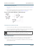
DC voltage supply faults
Fan P/S fault
The 48 V power supply used for the fans is monitored. A fault will be reported if the voltage varies by
more than ± 10%.
RF drive P/S fault
The 62 V power supply used for the RF drive is monitored. A fault will be reported if the voltage
varies by more than ± 10%.