
Installation manual

XR6/XR3 Installation Manual Audio and IBOC inputs
Issue 3.0 2009-07-15 Page 8-5
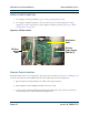
2. On the remote interface PWB, connect a jumper from J3-23, and a jumper from J3-25 to
ground (TB2-4) permanently (or through the remote system). This will enable the IBOC
inputs on Exciter A and B. A connecter shell and solder pins for J3 are provided in the
ancillary kit.
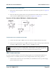
3. On the RF drive buffer PWB, set E3 to Low to select low sensitivity by shorting pins 2 and 3.
4. On the RF drive buffer PWB, set E1 and E2 to Ext, by shorting pins 2 and 3.
Routing IBOC Installation Cables
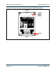
1. Route IBOC cables through the cable entry hole in the transmitter’s top panel. See Figure 8.3
on page 8-6).
2. Route the cables through the ferrite toroid provided in ancillary kit. Route the Mag cable
toward the remote interface PWB at the top of the transmitter, behind the GUI panel, and
route the Phase cable toward the RF drive buffer PWB at the bottom of the transmitter.
Connections for an IBOC installation
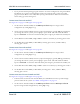
1. Connect the NE-IBOC Phase output to J14 on the RF drive buffer PWB (at the bottom of
the transmitter) using Cat 5 cable. See Figure 8.1 on page 8-2 .
2. Connect the NE-IBOC Mag output to J10 on the remote interface PWB (behind the GUI at
the top of the transmitter) using Cat 5 cable. See Figure 6.3 on page 6-4.