
Installation manual

XR6/XR3 Installation Manual Audio and IBOC inputs
Issue 3.0 2009-07-15 Page 8-3
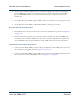
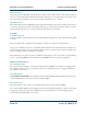
Routing Analog Installation Cables
1. Route audio cables through the cable entry hole in the transmitter’s top panel. See Figure 8.3
on page 8-6.
2. Route the cables through the ferrite toroid, provided in the ancillary kit, then toward the
remote interface PWB, behind the GUI panel (see Figure 6.3 on page 6-4).
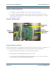
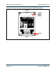
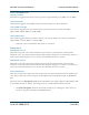
Figure 8.2: RF Drive Buffer PWB Details – IBOC Configuration
Connections for an analog installation
1. Connect the audio input to TB2 on the remote interface PWB, behind the GUI panel.
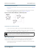
2. Ensure correct signal polarity for the TB2 connections in order to attain proper asymmetrical
modulation: TB2-1 is positive, TB2-3 is negative, and TB2-2 is ground.
IBOC Configuration
To ensure maximum reliability of the main analog program, the recommended installation is to
configure Exciter A for IBOC operation, and to configure Exciter B for analog operation.
• If both exciters are driven from the NE-IBOC, the NE-IBOC becomes a potential single
point of failure in the system.
Note: How you connect the audio cables’ shield depends on the presence or absence
of ground loops. In some installations, you may need to connect the shield at one
end only. In such cases, connect the end that provides the best results.