
Installation manual

XR6/XR3 Installation Manual Audio and IBOC inputs
Page 8-2 Issue 3.0 2009-07-15
Audio configuration
1. To configure an analog installation, go to “Analog Configuration” below.
2. To configure an IBOC installation, choose which exciter you will configure for analog
operation (A or B), and which you will configure for IBOC operation, then go to “IBOC
Configuration” on page 8-3.
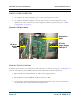
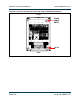
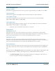
Figure 8.1: RF Drive Panel
Analog Configuration
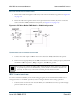
By default, both exciters are configured for analog operation as follows. See Figure 8.1 and Figure 8.2
(a detail of the RF drive buffer PWB schematic in the XR6/XR3 Troubleshooting Manual).
1.
E3 on the RF drive buffer PWB is set to HI to select high sensitivity.
2.
On the RF drive buffer PWB, E1 and E2 are both set to Int.
3. On the remote interface PWB, J3-23 and J3-25 should both be open circuit. See electrical
schematic
SD-1 in the XR6/XR3 Troubleshooting Manual.
RF Drive
Buffer
PWB
Distribution
PWB
RF Drive
Power Supply
PWB (62 V)