
Installation manual


XR6/XR3 Installation Manual Adjusting the spark gap
Issue 3.0 2009-07-15 Page 7-1
Section 7: Adjusting the spark gap
The XR6/XR3’s RF output filter contains a spark gap that must be adjusted - based on frequency and
site altitude - to provide protection against excessive voltage (i.e., lightning) on the RF output.
If the altitude of the transmitter site is known prior to transmitter delivery, then the spark gap is
adjusted at Nautel. If this is the case, it may only be necessary to verify the spark gap setting.
1. Determine the frequency of the transmitter (in kHz)
2. Determine the altitude of the transmitter site (in feet).
3. Make sure that the ac power is turned off at the ac service entrance.
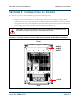
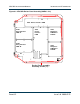
4. Gain access to the RF output spark gap, noting it is in the same vicinity as the RF output
connector (see “Preparation” on page 6-1).
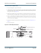
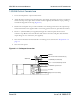
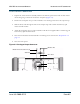
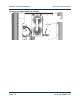
5. Locate spark gap E1 (see Figure 7.1 on page 7-2). Measure the air gap between the spark gap
balls, using a feeler gauge.
6. The air gap should be the distance listed in Table 7.1, “Spark Gap Setting versus Altitude”
for the carrier frequency (use the closest frequency except where the Note below differs)
multiplied by the scale factor listed in Table 7.2, “Altitude Scale Factor” on page 7-11 for the
altitude determined in Step 2. If not, loosen the locking nut on the spark gap, adjust the
position of the spark gap ball for the required gap and then tighten the locking nut.
7. Close access to the RF output filter’s access panel (see “Preparation” on page 6-1).
WARNING:
THE AC VOLTAGES PRESENT IN THE TRANSMITTER CAN BE FATAL. EXERCISE
EXTREME CAUTION.
Note:
Between certain 1 kHz increments there is a considerable difference in air gap. If
your frequency is 663 kHz, use the gap setting for 660 kHz. If your frequency is
664kHz, use the gap setting for 665 kHz. If your frequency is 1243 kHz, use the
gap setting for 1240 kHz. If your frequency is 1244 kHz, use the gap setting for
1245 kHz.