
Installation manual


XR6/XR3 Installation Manual Installing the RF connector
Issue 3.0 2009-07-15 Page 6-3
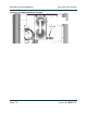
7/8 EIA Output Connection
1. Locate and unpack the output connector kit.
2. Attach the brass connector cup from the kit to the output strap using the M5 x 16 mm long
hex head bolt, split washer and flat washer supplied, such that the cup is pointing towards
the large hole in the top (Figure 6.2).
3. Position the stud plate on top of the transmitter over the large hole above the output strap
and attach with the four supplied M5 x 16 mm long pan head screws, split and flat washers.
4. Insert a 7/8 EIA Bullet (not supplied) through the connector plate into the brass connector
cup. Remove the three M6 nuts and washers from the stud plate and attach the output flange
or coax connector (not supplied).
5. Close the Exciter Panel and reinstall all 11 mounting screws removed in “Preparation” on
page 6-1.
6. Close the front panel.
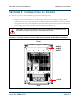
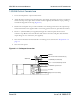
Figure 6.2: 7/8 EIA Output Connection
Stud Plate
7/8 EIA Cup Connector
M6 Nuts
M5 x 16 mm Panhead Screws (4)
7/8 EIA Bullet (not included)
Output Strap
M5 x 16 mm Hex Head Bolt