
Installation manual


XR6/XR3 Installation Manual Installing the RF connector
Issue 3.0 2009-07-15 Page 6-1
Section 6: Installing the RF connector
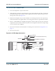
The XR6/XR3 comes with one of several types of RF output connectors. All types are illustrated in
this section.
Preparation
1. Make sure that the ac power is turned off at the ac service entrance.
2. Gain access to the Exciter Panel assembly by opening the door containing the GUI and
control panel on the front of the transmitter. The door is not latched and just swings open to
the left.
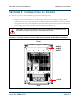
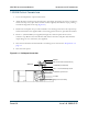
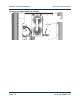
3. Remove all 11 Exciter Panel assembly mounting screws (Figure 6.1 on page 6-2), then swing
the Exciter Panel to the left to open it and expose the inside of the filter.
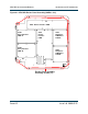
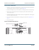
4. On the back wall of the filter, there is an Output Strap attached to one disc-shaped capacitor
(e.g., see Figure 6.2 on page 6-3 and the Note below). Perform the steps in the following
sections to install the appropriate RF output connector.
5. If you are proceeding to “Adjusting the spark gap” on page 7-1 after installing the RF
connector, leave the
Exciter Panel open until the completion of that procedure.
.
WARNING:
THE AC VOLTAGES PRESENT IN THE TRANSMITTER CAN BE FATAL. EXERCISE
EXTREME CAUTION.
Note:
The filter components shown in the RF connector figures in this section are
frequency-dependent. Therefore, the components used in your transmitter may not
exactly match the components shown in the figures.