
Installation manual

XR6/XR3 Installation Manual Unpacking and positioning
Issue 3.0 2009-07-15 Page 3-3
3. Move the transmitter cabinet to its assigned position.
4. Verify that the ac power cable conduit from the ac disconnect switch reaches the entry point
in the cabinet.
5. Verify that the RF feed cable reaches the RF output connector on the cabinet.
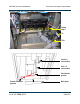
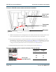
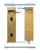
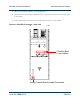
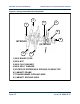
Figure 3.2: XR6/XR3 Transmitter – Rear View
2 Packing Bolts
Safety Ground Stud Assembly Connection
(1 per module)