
Installation manual

XR6/XR3 Installation Manual Installing the power transformer
Page 2-6 Issue 3.0 2009-07-15
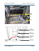
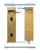
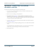
Figure 2.5: XR6/XR3 1-phase power transformer installation
9. Slide the transformer into its final position in the cabinet. Ensure that the anchor holes in the
base of transformer line up with the anchor holes in the bottom of the transmitter.
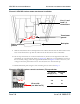
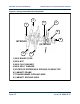
10. Set the tap connections on control transformer T2, located on the right-hand wall of the
transmitter (as viewed from the back, see Figure 2.3). Based on your nominal line to line (or
line to neutral) voltage, select the tap position identified in Figure 2.6 that is closest to your
voltage. If necessary, disconnect wire # 141 and secure it to the selected tap.
11. Reinstall the back plate using the four mounting screws removed in Step 3.
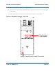
Figure 2.6: XR6/XR3 1-phase control transformer (T2) tap selection
Line 1, 2 and
Load 1, 2
connections
Transformer
ground
Back plate
Station reference
ground
L-L or L-N
Voltage (V ac)
Wire #141
Tap
277 H4
240 H3
208 H2
H4 H3
H2 on side
(see label on T2)