
Installation manual

XR6/XR3 Installation Manual Installing the power transformer
Page 2-4 Issue 3.0 2009-07-15
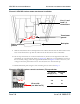
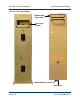
3. Remove the back plate at the bottom/back of the transmitter cabinet by removing four
mounting screws (see Figure 2.4 on page 2-5).
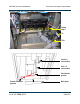
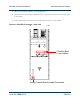
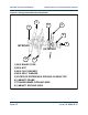
4. For single-phase transmitters only: Remove the four choke shims at the bottom of the tray
supporting the three chokes. The shims are secured using M5 hardware (see Figure 2.3).
Discard shims and hardware or retain for future shipping of the transmitter..
5. Position the power transformer assembly directly behind the cabinet, with its Line/Load
terminals and voltage taps facing the right side, as viewed from the rear (see Figure 2.4).
6. With the help of an assistant, lift the end of the power transformer closest to the cabinet
slightly, slide the transformer part way into the cabinet, then lower it onto the transmitter’s
bottom plate. Be sure to leave enough room to easily connect the Line, Load and
Transformer Ground wires.
7. For three-phase transmitters, connect the nine wires terminated on contactors K1 and K2 to
the transformer’s
Load terminals – H1 90, H2 90, H3 90, H1 150, H2 150, H3 150, H1 244, H2
244
, and H3 244. Be sure to connect the wires to the correct load terminals, 90 V, 150 V and
244 V, as marked on the transformer (see Figure 2.1 on page 2-1). For single-phase
transmitters, connect the two black, 6 AWG wires terminated on A14U1-1 and A14U2-1 to
the transformer’s Load 1 and Load 2 terminals respectively; connect the two black, 6 AWG
wires terminated on A14U3-2 and TB1-1 to the transformer’s Line 1 and Line 2 terminals
respectively (see Figure 2.2 on page 2-2).
8. For three-phase transmitters, connect the ac line input to the X1 (Line 1), X2 (Line 2) and X3
(Line 3) input terminals on the transformer (see Figure 2.1 on page 2-1). The ac ground will
be connected later. For single-phase transmitters, connect the ac line input to TB1-2 (Line 1),
TB1-1 (Line 2 or Neutral) and TB1-4 (ground), noting terminal block TB1 is in the lower,
right part of the cabinet (see Figure 2.3 on page 2-5).