
Installation manual

XR6/XR3 Installation Manual Installing the power transformer
Issue 3.0 2009-07-15 Page 2-1
Section 2: Installing the power
transformer
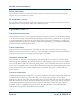
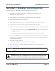
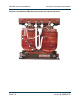
1. Before placing the transformer into the transmitter, set the line voltage tap selections. Based
on your nominal line to line (or line to neutral for some single-phase ac power sources)
voltage, select the appropriate tap position identified on the labels mounted on the terminal
board end of the transformer. One label identifies the tap number and the line-to-line (or
line-to-neutral) voltage. Another label identifies the tap. All phases must be set to the same
tap (see also Figure 3.1 and Table 2.1 on page 2-3). If necessary, use the hardware already on
each of the three copper straps to connect the straps to the new tap positions. Be sure to
scrape any excess epoxy off the electrical joint area.
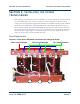
Transformer taps
Figure 2.1: Three-phase XR6 power transformer line voltage tap layout
1
2
3
4
5
6
LOAD 3
LINE 3
LOAD 2
LINE 2
LOAD 1
LINE 1
244 V Load Terminals 150 V Load Terminals
90 V Load Terminals