
Installation guide

XR6/XR10 Installation Guide Digital Monitoring Products
3
INTRODUCTION
System Components
3.1 Description
The DMP system is made up of an alarm panel with built in communicator, an enclosure, a 16.5 VAC transformer, and a
12 VDC 7.0 Ah battery. You can add Security Command keypads to the system and can also connect auxiliary devices to
the panel's open collector outputs to expand the basic system. Combined current requirements of additional modules
may require an auxiliary power supply. Refer to the Standby Battery Power Calculation section in this guide when
calculating power requirements. In addition, up to 4 points of zone expansion can be added to the XR6.
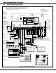
3.2 Wiring Diagram
The system wiring diagram in Figure 1 shows some of the accessory devices you can connect for use in various
applications. A complete description of each module follows. Zone expanders as well as wireless zones can be added to
the XR6.
3.3 Lightning Protection
Metal Oxide Varistors and Transient Voltage Suppressors help protect against voltage surges on input and output
circuits. A transorb is provided for the Smoke Detector Output Circuit (Terminal 11). This transient protection provides
additional resistance to electrical surges such as lighting. Additional surge protection is available by installing the DMP
370 or 370RJ Lightning Suppressors.
3.4 Command Processor Accessories
You can connect any combination of up to four Model 670, 770, and 771 vacuum fluorescent, 790, 791, and 793 LCD, or
692 LED Security Command Keypads to the 4-wire keypad data bus provided by the panel on terminals 7, 8, 9, and 10.
Also, you can connect Model 714, 715, 714-8, 714-16, 715-8, 715-16 zone expanders to the XR6 keypad bus.
Additionally, you can connect one Model 738A Ademco Interface Module or one Model FA426 Wireless Receiver to the
XR6 keypad bus.
Note: The XR10 does not support zone expansion on the keypad bus.