
Installation guide


XR6/XR10 Installation Guide Digital Monitoring Products
19
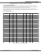
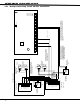
WIRING DIAGRAMS
RJ31X Telco Jack
7
10
13
MAIN BACKUP
Telephone Connections
1 2 3 4 5 6
Panel Auxiliary Power - Terminal 7
Note 1
Note 1
DCX Systems
STU-2Z
Note 1: Use EOL Termination
Assembly P/N 21024-0001
(2.2k
W 1/2 W Resistor).
Use EOL Termination
Assembly P/N 21024-0003
(590 W 1/2 W Resistor).
S
S
S
Panel Common - Terminal 10
Supervisory Zone Input - Terminal 13
= Supervised CircuitS
1
2
3
4
J11
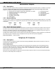
23.2 Installation for Derived Channel burglary