
Installation guide


Digital Monitoring Products XR6/XR10 Installation Guide
18
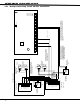
WIRING DIAGRAMS
S
AUXILIARY
POWER
SUPPLY
12 or 24 VDC
5 Amp Maximum
Power Supply
Trouble Contacts
N/C
NOTE: If an auxiliary supply is not used,
terminals 3 and 4 on the 866 Indicating
Circuit Module can be jumpered together
to supply bell power from the XR20 panel.
A maximum of 1.5 Amps at 12 VDC is
available from terminal 5 of the XR20.
Each 866 Indicating Circuit Module
in alarm draws up to 35mA from its
terminal 3 alarm input.
AC
1 234 5678 10111213141516171819
AC +B -B BELL GND SMK
GND
9
RED YEL
GRN BLK
20 21 22 23 24 25 26 27
GND GND GND GND
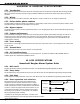
The Auxiliary Power Supply and Indicating Circuit Module
trouble contact zone must be programmed as a Supervisory
Type zone and must be selected for display in the keypad
status list.
= Supervised Circuit
S
S S
S S
1
2
3
4
5
6
7
8
Auxiliary Power
Ground
Alarm Input
Bell Power + Input
Bell Power Ð Input
Bell A + Output -
Bell A Ð Output
Bell B + Output
Bell T rouble
Bell T rouble
Bell B Ð Output
9
10
11
UL Listed, Polarized
Indicating Devices.
Style Z
Notification Circuit Module
DMP Model 865
85mA at 12 VDC
AUXILIARY
POWER
SUPPLY
Power Supply
Trouble Contacts
N/C
12 or 24 VDC
5 Amp Maximum
S
S
1
2
3
4
5
6
7
8
Auxiliary Power
Ground
Alarm Input
Bell Power Input
Bell Output +
Bell Output -
Bell T rouble
Bell T rouble
UL Listed, Polarized
notification Devices.
10k
Ω
EOL Resistor
DMP Model 308
Notification Circuit Module
DMP Model 866
37mA at 12 VDC
1k
Ω
Optional Module installation
Each 865 Notification Circuit Module
in alarm draws up to 85mA from its
terminal 3 alarm input.
S
S
S
S
S
S
S
S
S
S
Style W
J16
Command Processor Reset
Phone Jack Connector
EPROM Socket
U11
J11
1
2
3
4
J4
Z1 Z2 Z3 Z4 Z5 Z6 Z7 Z8 Z9 Z10+ Z10-
Notification Circuit Module
DMP Model 866
45mA at 12 VDC
Notification Circuit Module
DMP Model 865
26mA at 12 VDC
23.1 Multiple Indicating Circuit Module Installation