
Installation guide


INSTALLATION
Digital Monitoring Products XR6/XR10 Installation Guide
12
Annunciator Outputs
12.1 Description
The four annunciator outputs can be programmed to indicate the activity of the panel's zones or conditions occurring on
the system. Annunciator outputs do not provide a voltage but instead switch to ground voltage from another
source. The outputs can respond to any of the conditions listed below:
1) Activation by zone condition: Steady, Pulse, Momentary, or Follower 7) Exit and Entry timers
2) Manually from the Security Command keypad 8) System Ready
3) Communication failure 9) Ground start activation
4) Armed area annunciation 10) Cellular Backup
5) Fire Alarm or Fire Trouble 11) Late to Close
6) Ambush alarm
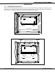
12.2 Harness Wiring
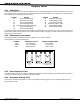
The open collector outputs are accessible by installing the DMP 300 Harness on the 4-pin header labeled J11. The output
locations are shown below. For UL applications, devices connected to the outputs must be located within the same room
as the panel.
Output Color Wire Output Color Wire
1 Red 1 3 Green 3
2 Yellow 2 4 Black 4
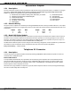
12.3 Model 860 Relay Module
You may connect a Model 860 Relay Module to the panel to provide relays for the annunciator outputs. These relays can
be used for electrical isolation between the alarm panel and other systems or for switching voltage to control various
functions. The module includes one relay and provides three additional sockets for expansion of up to four relays. A 4-
wire harness is also provided that connects the Model 860 to the DMP panel.
The 860 mounts inside the panel enclosure using the 3-hole mounting configuration. Plastic standoffs are provided with
the module for ease of installation. Power is supplied to the relay coils from the panel's keypad bus.
Relay Contact Rating: 2 Amps @ 30 VDC
Telephone RJ Connector
13.1 Description
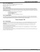
Connect the panel to the public telephone network by installing a DMP 356 RJ Cable between the panel's J4 connector
and the RJ31X or RJ38X phone jack.
Phone Cable Monitor
A two pin header labeled RJ SUP (J7) is provided to allow monitoring of the telephone cable connected between the
panel and a RJ38X jack (pins 2 & 7 jumpered). Attach a DMP Model 306 Harness between J7 and any available zone.
The pins of J7 are connected via the telephone cable to 2 & 7 of the RJ38X jack. The RJ38X jack provides a jumper
between pins 2 & 7 which completes the circuit.
When the zone is programmed for a Supervisory type (SV) and the telephone cable is removed, the keypad will display
the zone in trouble and produce a steady tone.