
Installation guide


XR6/XR10 Installation Guide Digital Monitoring Products
9
INSTALLATION
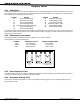
Bell Output
7.1 Terminals 5 and 6
Nominal 12 VDC is supplied by terminal 5 on the panel to power alarm bells or horns. The output is rated for a
maximum of 1.5 Amps with a 40VA transformer and 600mA with a 20VA transformer. This output can be steady, pulsed,
or Temporal Code 3 depending upon the Bell Action specified in Output Options programming. Terminal 6 is the ground
reference for the bell circuit.
Keypad Data Bus
8.1 Description
Terminals 7, 8, 9, and 10 of the panel are designated as the keypad data bus. In addition to keypads, the XR6 allows
the connection of four zones on address one: zone expanders, 5845LX Glassbreak Detectors, 6155LX PIRs, and DS775LX
PIRs.
8.2 Terminal 7 - RED
Nominal 12 VDC is supplied at terminal 7 to power Security Command keypads and zone expanders. This is also where
power for any auxiliary device is supplied. The ground reference for terminal 7 is terminal 10. The maximum output is
rated at 500mA. All auxiliary devices totaled together must not exceed the panel's maximum current rating of 500mA.
8.3 Terminal 8 - YELLOW
Data receive from keypads and zone expanders.
8.4 Terminal 9 - GREEN
Data transmit to keypads and zone expanders.
8.5 Terminal 10 - BLACK
Terminal 10 is the ground reference for Security Command keypads, zone expanders, and any auxiliary devices being
powered by terminals 7 and 11.
8.6 Programming Connection
A locking four pin header (J8) is provided to connect a keypad when using a DMP Model 330 Programming Cable. This
provides a quick and easy connection for programming the panel.
Smoke and Glassbreak Detector Output
9.1 Terminal 11
Nominal 12 VDC at 100mA maximum (shared by terminal 25) is supplied at terminal 11 to power 4-wire smoke detectors
or other auxiliary powered devices. This output can be turned off by the user for 5 seconds using the Sensor Reset
Menu Option. Terminal 10 is the ground reference for terminal 11.