
Installation guide

Digital Monitoring Products XR6/XR10 Installation Guide
4
INTRODUCTION
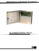
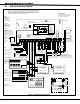
Figure 1: XR6/XR10 Wiring Diagram
Keypads
Models 670, 770, 771
100mA @ 8 - 16 VDC
125mA with display lit
Models 690, 790,
791, 793
100mA @ 8 - 16 VDC
Model 692
75mA @ 8 -16 VDC
Bell
10.4 - 13.2 VDC
Total current:
1.5 Amps max. w/ 40
VA
600mA w/ 20 VA
Household System
An alarm sounding
device must be
installed indoors so
that it is clearly
heard in all sleeping
areas.
Bell
DMP
transformers:
Model 320
16.5 VAC 40VA
Class 2 wire-in
Model 321
16.5 VAC 40VA
Class 2 plug-in
Model 324
Plug into
120 VAC
outlet
not
controlled
by
switch.
16 - 18 gauge
wire
Cold Water Pipe Earth
Ground
Maximum AC wire
distance
With 16 gauge wire: 70
feet
With 18 gauge wire: 40
feet
Output Header J11
All outputs must be connected to
devices located within the same
room as the control panel.
Use DMP Model 300 Harness.
Front Tamper
Rear Tamper
Tamper protection
when required for
Model 350A Attack
Resistant Enclosure.
Zone 10 compatibility
identifier: A
Maximum operating range:
8.8 VDC - 14.2 VDC.
See the XR6/XR10 Installation
Guide (LT-0229) for a list of
approved 2-wire smoke detectors.
Heat detectors, manual pull
stations, or any other shorting
device. Unlimited number of
units.
2-wire
smoke
detector
4-wire smoke
detector
Power
Supervision
Relay
Up to 500mA auxiliary
current at 10.4 - 13.2
VDC from Terminal 7.
Smoke Output
100mA @ 10.4 - 13.2
VDC Terminal 11
3.3k Ω
DMP Model 309
Command Processor Reset
Phone Jack Connector
PROG
Programmer Header J8
Use DMP Model 330 Harness
RJ Cable Monitor J7
Use DMP Model 306 Harness
J4
J7
J8
J16
J11
U11
RJ SUP
1
2
3
4
EPROM
Socket
+ -
Smoke
Detector
22 GA. MIN BLACK
22 GA. MIN GREEN
22 GA. MIN YELLOW
22 GA. MIN RED
ZONE 5
ZONE 6
ZONE 4
ZONE 7
ZONE 8
ZONE 9
ZONE 10
ZONE 2
ZONE 1
ZONE 3
1K Ω
1K Ω
BLACK
RED
1K Ω
1K Ω
1K Ω 1K Ω
1K Ω
1K Ω
1K Ω
AC AC +B -B BELL GND RED YEL GRN BLK SMK Z1 GND Z2 Z3 GND Z4 Z5 GND Z6 Z7 GND Z8 Z9 Z10+ Z10-
Red
Black
Secondary Power
Supply
1.2 Amps max. charging
current. Use only 12 VDC
rechargable batteries.
DMP Model 367. Replace
every 3 - 5 years.
XR6 only
ZONE EXPANDER
Model 714
15mA @ 12 VDC
Models 714-8, 714-16
20mA @ 12 VDC
ZONE EXPANDER
Model 715
15mA @ 12 VDC
Models 715-8, 715-16
20mA @ 12 VDC
AC wiring must be in conduit and
exit
out the left side of the panel
enclosure
Wiring on
terminals 5
through 17
must exit to
the right and
maintain a 1/
4" separation
from the AC
and battery
positive wiring.
Detail for XR6 only
See detail below
for XR6 panel
only
Z3 GND Z4 Z5
Z6+ Z6-
ZONE 6
ZONE 5
2-wire
smoke
detector
ZONE 4
A B C D E F G H I J K L
V W XM N O P Q R S T U
YZ
COMMAND
SPEC I AL
STAY
INSTAN T
BYPASS
CODE
90
1234
56
7
8
6 7 8 9 10
1 2 3 4 5
INSTANT
STAY
ARMED
TRBL
POWER
READY
16.5 VAC 20VA
Class 2 plug-in
The Class 2, Class 3, and power-limited fire alarm circuits are installed using CL3,
CL3R, or CL3P, or substitute cable permitted by the National Electric code, ANSI/
NFPA 70, and the Class 2, Class 3, and power-limited fire alarm circuit conductors
extending beyond the cable jacket are separated a minimum of 1/4 in. or by
nonconductive tubing or by a nonconductive barrier.
3.5 XR6/XR10 Wiring Diagram