XR6/XR10/XR20 Command ProcessorTM Panels Installation Guide 6/10/26 Zone Burglary/Fire/Access Control Panels with Built-in Communicator 2841 E.
MODEL XR6/XR10/XR20 COMMAND PROCESSORTM INSTALLATION GUIDE FCC NOTICE This equipment generates and uses radio frequency energy and, if not installed and used properly in strict accordance with the manufacturer's instructions, may cause interference with radio and television reception.
TABLE OF CONTENTS Section Page Panel Specifications 1.1 Power supply ................................................................................................. 1 1.2 Communication .............................................................................................. 1 1.3 Panel zones ................................................................................................... 1 1.4 Keypads ................................................................................................
TABLE OF CONTENTS Section Page 13.2 FCC registration ............................................................................................ 12 13.3 Notification ..................................................................................................... 12 13.4 Ground start .................................................................................................. 13 Reset Jumpers J16 14.1 Description ...................................................................................
Introduction Panel Specifications 1.1 Power supply Transformer Input: 16.5 VAC 40VA (Models 320 wire-in or 321 plug-in) 16.5 VAC 20VA (Model 324 plug-in) Standby Battery: 12 VDC 7.0Ah (40VA transformer charges up to 2 batteries) Auxiliary Output: 12 VDC at 500mA Bell Output: 12 VDC at 1.5 Amps with 40VA transformer, 600mA with 20VA transformer Smoke Detector Output: 12 VDC at 100mA All circuits inherent power limited 1.
Introduction Introduction 2.1 Description The DMP XR6/XR10/XR20 Command Processors are powerful 12 VDC burglary and fire communicator panels with battery backup. The XR10/XR20 provide nine on-board burglary zones and one on-board 12 VDC Class B powered fire zone. The XR6 provides five burglary and one fire zone. The fire zone has a reset capability to provide for 2-wire smoke detectors, relays, or other latching devices.
Introduction System Components 3.1 Description The DMP XR6/XR10/XR20 system is made up of an alarm panel with built in communicator, an enclosure, a 16.5 VAC transformer, and a 12 VDC 7.0 Ah battery. You can add up to four Security Command keypads to the system and can also connect auxiliary devices to the panel's open collector outputs to expand the basic system. Combined current requirements of additional modules may require an auxiliary power supply. Refer to section 6.
Introduction Output Header J11 All outputs must be connected to devices located within the same room as the control panel. DMP transformers: Model 320 16.5 VAC 40VA Class 2 wire-in Use DMP Model 300 Harness.
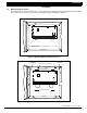
Installation Installation 4.1 Mounting the enclosure The metal enclosure must be mounted in a secure, dry place to protect the panel from damage due to tampering or the elements. It is not necessary to remove the PC board when installing the enclosure.
Installation 4.2 Mounting keypads Security Command keypads have removable covers that allow you to easily mount the base to a wall or other flat surface using the screw holes provided on each corner. For mounting keypads on solid walls, or for applications where conduit is required, use a DMP 695, 696, 775, or 776 keypad conduit backbox. 4.3 Wiring keypads Keypad data bus The keypad data bus consists of a 4-wire cable that provides 12 VDC power, data in, data out, and a panel common.
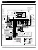
Installation Secondary Power Supply 6.1 Battery terminals 3 and 4 Connect the black battery lead to terminal 4 on the panel and to the negative terminal of the battery. The negative terminal connects to the enclosure ground internally through the XR6/XR10/XR20 circuit board. Connect the red battery lead to terminal 3 on the panel and to the positive terminal of the battery. Observe polarity when connecting the battery. The panel can charge up to two batteries.
Installation XR6/XR10/XR20 STANDBY BATTERY POWER CALCULATIONS Standby Current Command Processor Panel Active Zones 1-9 Active Zone 10 (zone 6 on XR6) 2-Wire Smoke Detectors Qty _____ x Qty _____ x 50mA 1.6mA 4mA .1mA Alarm Current ______ mA ______ mA Qty _____ x ______ mA ______ mA Qty _____ x Bell Output 50mA *2mA 30mA .1mA ______ mA ______ mA ______ mA ______ mA 1500mA max.
Installation Bell Output 7.1 Terminals 5 and 6 Nominal 12 VDC is supplied by terminal 5 on the panel to power alarm bells or horns. The output is rated for a maximum of 1.5 Amps with a 40VA transformer and 600mA with a 20VA transformer. This output can be steady or pulsed depending upon the Bell Action specified in Output Options programming. Terminal 6 is the ground reference for the bell circuit. Keypad Data Bus 8.
Installation Burglary Zones 10.1 Description The XR10/XR20 terminals 12 to 24 are the nine burglary zones. For programming purposes, the zone numbers are 1 to 9. The zone configurations on terminals 12 to 24 are described below. The XR6 terminals 12 to 18 are the five burglary zones with terminal 16 providing the ground for zone 5.
Installation Powered Zone for 2-Wire Smoke Detectors 11.1 Terminals 25 and 26 A resettable 2-wire Class B powered zone is provided on terminals 25 (positive) and 26 (negative) of the panel. For programming purposes, the zone number is 10 on the XR10/XR20 and zone 6 on the XR6. The zone uses a Model 309, 3.3k W EOL resistor (provided with the panel) and has an operating range of 8.8 to 14.2 VDC. Power is dropped from zone 10 any time a Sensor Reset is performed on the panel.
Installation Annunciator Outputs 12.1 Description The four annunciator outputs can be programmed to indicate the activity of the panel's zones or conditions occurring on the system. Annunciator outputs do not provide a voltage but instead switch to ground voltage from another source.
Installation 13.4 Ground start To configure the XR6/XR10/XR20 for ground start operation, you must install the appropriate ground start module and program one of the panel's available annunciator outputs for Ground Start operation. Refer to the XR6/XR10/XR20 Programming Guide for complete programming information. This option must not be selected on a UL listed system. Reset Jumpers J16 14.1 Description There are two reset jumpers located at the top right of the panel's circuit board labeled RESET.
Installation UL 1023 SPECIFICATIONS Household Burglar-Alarm System Units 16.1 Bell cutoff The bell cutoff time cannot be less than five minutes. See section 7.2 of the XR6/XR10 Programming Guide (LT-0230) and XR20 Programming Guide (LT-0305). 16.2 Entry delay The maximum entry delay used must not be more than 45 seconds. See section 6.4 of the XR6/XR10 Programming Guide (LT-0230) and XR20 Programming Guide (LT-0305). 16.3 Exit delay The maximum exit delay used must not be more than 60 seconds.
Installation UL 1635 SPECIFICATIONS Digital Burglar Alarm Communicator System Units 18.1 Digital Dialer telephone number Both programmed telephone numbers must begin with a D or P. See sections 3.17 and 3.18 of the XR6/XR10 Programming Guide (LT-0230) and XR20 Programming Guide (LT-0305). 18.2 Entry delay The maximum entry delay used must not be more than 60 seconds. See section 6.4 of the XR6/XR10 Programming Guide (LT-0230) and XR20 Programming Guide (LT-0305). 18.
Installation UNIVERSAL UL and NFPA FIRE ALARM SPECIFICATIONS 20.1 Introduction The programming and installation specifications contained in this section must be completed when installing the Model XR6/XR10/XR20 in accordance with any of the UL or NFPA fire standards. Additional specifications may be required by a particular standard. 20.2 Wiring All wiring must be in accordance with NEC, ANSI/NFPA 70. 20.
Troubleshooting CALIFORNIA STATE FIRE MARSHAL SPECIFICATIONS 22.1 Bell output definition The bell output of the Model XR6/XR10/XR20 must be programmed to operate steady on burglary alarms and temporal on fire alarms. See sections 7.4A and 7.4B of the XR6/XR10 Programming Guide (LT-0230) and XR20 Programming Guide (LT-0305).
XR6/XR10/XR20 Installation Guide E. Industrial Drive Springfield, MO 2841 E.