Programming Guide XR5FC/XR5SL Fire Command Processor™ Panels
PANEL PROGRAMMER MODEL XR5FC / XR5SL FIRE COMMAND PROGRAMMING GUIDE When using the XR5FC/XR5SL panel for any listing organization's approved methods, refer to this manual and the Specifications Compliance section of the XR5FC/XR5SL Installation Guide (LT-0299). These documents outline the installation and programming requirements of all applications for which the XR5FC/XR5SL is approved.
Table Of Contents Introduction.......................................................................1 1.1 1.2 1.3 1.4 1.5 1.6 1.7 1.8 1.9 Before You Begin..................................................................... 1 About this Guide..................................................................... 1 Reading the Contents.............................................................. 1 Programming Information Sheets............................................. 1 Getting Started...............
Table of Contents Output Options................................................................11 6.1 6.2 6.3 6.3.1 6.3.2 6.3.3 6.4 6.4.1 6.4.2 6.4.3 6.4.4 6.4.5 Output Options......................................................................11 Bell Cutoff Time.....................................................................11 Bell Action.............................................................................11 Fire..............................................................................
Introduction Introduction 1.1 Before You Begin About this Guide This guide provides programming information for the DMP XR5FC and XR5SL Fire Command™ Panels. After this introduction, the remaining sections describe each programming menu item function and its available options. The XR5FC and XR5SL panels contain all programming information in an on-board processor and do not require an external programmer.
Introduction 1.3 Programming Menu There are 8 programming menu items from which to choose: Menu Item Section in this guide Initialization 2 Communication 3 Remote Options 4 System Options 5 Output Options 6 Zone Information 7 Stop 8 Set Lockout Code 9 To select a section for programming, press any top row Select keys when the keypad displays the name of that section. Detailed instructions for each programming step are found in sections 2 through 9 of this guide. 1.
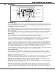
Introduction 1.6 Special Keys Fire Command Center Function Keys LCD Display POWER TROUBLE ALARM SILENCE RESET ABC TEST MNO DEF 1 GHI 2 JKL 3 4 ENABLE DRILL PQR STU 5 6 9 0 YX Select Keys VWX 7 8 COMMAND COMMAND Key Back Arrow Key COMMAND Key Pressing the COMMAND key allows you to go forward through the programming menu and through each step of a programming section.
Introduction 1.7 Entering Alpha Characters Some programming options allow you to enter alphanumeric names. To enter an alpha character, press the key that has that letter written below it. The keypad displays the key number. Next, press the Select key that corresponds to the location of the letter under the key. Pressing a different Select key changes the letter. When another digit key is pressed, the last letter displayed is retained and the process starts over.
Initialization Initialization 2.1 INITIALIZATION Initialization The Initialization function allows you to set the panel programmed memory back to the factory defaults in preparation for system programming. After you select YES to clear part of the memory, the panel asks if you are sure you want to clear the memory. This is a safeguard against accidently erasing part of your programming. No memory is cleared from the programming until you answer yes to the SURE? YES NO prompt. 2.
Communication Communication 3.1 Communication COMMUNICATION This section allows the communication settings for the XR5FC and XR5SL panels to be configured. After choosing the Communication Type, continue through the list of additional communication options. 3.2 COMM TYPE: NONE This specifies the communication method the panel uses to contact the receiver. Press any Select key to display the following communication options: CID NONE - For local systems.
Communication 3.10 BACKUP 3.11 First Phone No: - First Telephone Number Second Phone No: - Second Telephone Number 3.12 NO YES Backup Reporting YES enables Receiver 1 to be a backup to Receiver 2 in the event the panel cannot contact Receiver 2. This is the first number the panel dials when sending reports to this receiver. A phone number can consist of two lines of 16 characters to equal 32 characters. You can program a three second pause in the dialing sequence by entering the letter P.
Communication 3.19 First Phone No: - First Telephone Number 3.20 Second Phone No: - Second Telephone Number 3.21 PAGER ID NUMBER - Pager Identification Number Digital Monitoring Products 8 This is the first number the panel dials when sending reports to this receiver. A phone number can consist of two lines of 16 characters to equal 32 characters. You can program a three second pause in the dialing sequence by entering the letter P. You can program a dial tone detect by entering the letter D.
Remote Options Remote Options 4.1 Remote Options REMOTE OPTIONS This section allows the information needed for Remote Command/Remote Programming operation to be entered. A description of the Remote Options follow. Note: A complete functional checkout of the panel is required following any programming or reprogramming. 4.
System Options System Options 5.1 System Options SYSTEM OPTIONS This section allows you to select system wide parameters used in the operation of the XR5FC and XR5SL system. 5.2 CRS ZONE TM: 0 Cross Zone Fault Time Enter the time allowed after a zone trips to indicate a zone fault condition. When a zone programmed for cross zoning trips, the panel begins counting down the Cross Zone Fault Time you enter here.
Output Options Output Options 6.1 Output Options OUTPUT OPTIONS This function allows you to program the panel Bell Output functions and certain Output options for the Form C relays and annunciator outputs. Form C relay outputs are available on the panel 6-position terminal strip. Annunciator outputs (open collector) are available by using the 4-wire output header on the XR5FC and XR5SL board. Refer to the XR5FC and XR5SL Installation Guide (LT-0299) for complete information.
Output Options 6.4.4 FIRE ALR OUT: 0 Fire Alarm Output This output is turned on any time a fire type zone is placed in alarm. The output is turned off using the Sensor Reset option when no additional fire type zones are in alarm. Enter 0 (zero) to disable this output. 6.4.
Zone Information Zone Information 7.1 ZONE INFORMATION Zone Information This allows you to define the operation of each protection zone used in the system. A description of each programming option follows: 7.2 ZONE NO: Zone Number – Enter the zone number to program. Press COMMAND to enter a zone name. Address Panel 3 Programming Zone Number 1-5 31-34 Note: At least one 630F keypad is required to support alarm display of zones 31-34. 7.
Zone Information 7.5 NEXT ZN? 7.6 alarm action . . . . NO YES Next Zone? When YES is selected, the programming for the zone terminates and the display returns to ZONE NO: - allowing you to enter a new zone number. To make changes to the Alarm Action for a zone, answer the NEXT ZONE? prompt with NO. The Alarm Action is then defined in the following sections. Alarm Action The Alarm Action section allows you to change or confirm the default alarm characteristics of a zone type.
Zone Information 7.8 Armed open ARMED OPEN Defines the action taken by the panel when the zone is placed into an open condition. There are three actions to define: the Message to transmit, which Relay output to activate, and the Relay output action. 7.8.1 Message to Transmit MSG: TROUBLE You can send two report types to the receiver: Alarm and Trouble. These are represented by the characters A and T. Press any top row Select key to display the zone full reporting options.
Zone Information 7.9 SWGR BYP: NO YES Swinger Bypass YES allows the zone to be bypassed by the panel after three alarm, trouble, or local trips within one hour. Selecting NO disables swinger bypassing for this zone. After the first trip, if the zone does not trip two more times within an hour, the bypass trip counter returns to zero. To automatically bypass it, the zone must trip a full three times within a subsequent hour. A report of the swinger bypass is automatically sent to the receiver.
Stop Stop 8.1 STOP Stop At the STOP prompt, press any Select key to exit the XR5FC or XR5SL panel programmer function. When selected, the panel performs an internal reset and exits the programmer. The Stop function clears the panel Status List. During the Stop function, all keypad displays are momentarily blank for two seconds. Afterwards, the programming function is terminated and the keypads return to the Status List display. Set lockout code Set Lockout Code 9.
Appendix Appendix 10.1 Keypad Status List The Status List is the current status of the system or records of recent system events that display on the alphanumeric keypads. If an event occurs on the system, such as an AC failure, the keypad displays the AC POWER -TRBL message. This is a system event that is placed into the Status List to alert the user to a problem. Some Status List items remain in the display until manually cleared and some are cleared automatically when the condition returns to normal.
Appendix 10.4 Walk Test The XR5FC and XR5SL panels provide a walk test feature that allows a single technician to test the protection devices connected to zones on the system. To conduct the Walk Test: From the 630F Keypad 1. From the keypad, enter the code 8144. If the system is monitored and the communication type is set to DD, the system sends a System Test Begin report to the central station. The keypad then displays WALK TEST for four seconds followed by TRIPS: X X X END.
Revisions Revisions to this Document This section explains the changes made to this document during this revision. This section lists the date the change was made, the section number and section heading, and a brief explanation of the change. Date Section Number and Heading 1.01 1.6 Special Keys 4.4 Armed Rings 5.4 Power Fail Delay 7.2 Zone Number 7.7 Zone Type Specifications 10.3 2-Button Panic Keys 10.4 Walk Test 10.7 Serviceman Programmer Access 10.8.
This page intentionally left blank XR5 Programming Guide Digital Monitoring Products 21
FCC Part 15 FCC Part 68 Registration ID CCKUSA-18660-AL-R California State Fire Marshal (CSFM) New York City (MEA) Underwriters Laboratories (UL) Listed ANSI/UL 864 Fire Protective Signaling 800-641-4282 INTRUSION • FIRE • ACCESS • NETWORKS www.dmp.com 2500 North Partnership Boulevard Made in the USA Springfield, Missouri 65803-8877 9073 LT-0312 1.01 © 2009 Digital Monitoring Products, Inc.