
Installation guide


Page 5
Installation
2841 E. Industrial Drive Springfield, MO 65802-6310 800-641-4282
XR5FC/XR5SL Installation Guide
Installation
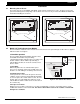
4.1 Mounting the enclosure
The metal enclosure for the XR5FC and XR5SL panels must be mounted in a secure, dry place to protect the
panels from damage due to tampering or the elements. It is not necessary to remove the XR5FC or XR5SL PC
board when installing the enclosure.
4.2 Model 377 Trouble Annunciator Module
The 377 module is installed on the enclosure door and connects to the panel through a 4-wire harness supplied
with the module. See Figure 4.
377 module operation
The 377 Trouble Annunciator Module provides visual
and audible annunciation of System Okay,
communication trouble, and panel processor failure. The
module contains a Green LED for System Okay, a
Yellow LED for Trouble, an electronic sounder, and a
Silence switch.
System Okay
When both phone lines are normal and the panel
processor is operating, only the Green LED on the 377
module is on. This LED goes off during a Sensor Reset.
Communication trouble
If either phone line connected to the panel is in a bad
condition, or if the panel has made TEN failed attempts
to send a report to the central station receiver, the 377
module emits a steady audible alert and turns on the
Yellow LED. The Silence switch can be used to turn off
the sounder only.
Panel processor failure
During a processor failure on the panel, or a remote programming session, the 377 module emits a steady
audible alert and turns on the Yellow LED. The Silence switch will not turn off the sounder or Yellow LED
during these conditions.
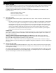
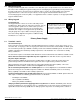
Figure 3A: XR5FC in standard Model 340FC enclosure.
J9 Command Processor Reset
U21
1
2
3
4
J12
RESET
EPROM Socket
J11
N/C COM N/O N/C COM N/O
K5
K4
Relay Sockets for Optional
Form C Outputs on J11
J10 Trouble Annunciator Header
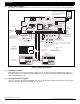
377 Trouble Annunciator Module
(Enclosure door mounted)
Green SYSTEM OKAY LED
SILENCE switch
Yellow TROUBLE LED
Alert sounder
Figure 4: 377 module wire harness
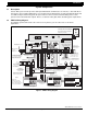
Figure 3B: XR5SL in standard Model 340SL enclosure.
AC
1
234
78
10 11 12
13
14
15
16
AC B+ B–
9
RED
YEL GRN
BLK
Z1B–
Z2 –
Z2+
U21
1
2
3
4
J12
Z1A–
Z1B+
Z1A+
MODEL XR5
MAIN
BACKUP
PANEL
RESET
EPROM Socket
J11
N/C COM N/O N/C COM N/O
J4
J5
Telephone Connections
5
6
BELL
SMK
OUTPUT 1
OUTPUT 2
SILENCE/RESET
PUSH FOR ONE SECOND
17
18
Z3 –
Z3+
19
20
Z4 –
Z4+
21
22
Z5 –
Z5+
Dual 3/4" x 1/2" Knockouts
Dual 3/4" x 1/2" Knockout
Two 1 3/4" Wire Openings
Extra Deep 3 3/4" Cabinet
AC
1
234
78
10 11 12
13
14
15
16
AC B+ B–
9
RED
YEL GRN
BLK
Z1B–
Z2 –
Z2+
U21
1
2
3
4
J12
Z1A–
Z1B+
Z1A+
MODEL XR5
MAIN
BACKUP
PANEL
RESET
EPROM Socket
J11
N/C COM N/O N/C COM N/O
J4
J5
Telephone Connections
5
6
BELL
SMK
OUTPUT 1
OUTPUT 2
SILENCE/RESET
PUSH FOR ONE SECOND
17
18
Z3 –
Z3+
19
20
Z4 –
Z4+
21
22
Z5 –
Z5+
Dual 3/4" x 1/2" Knockouts
Dual 3/4" x 1/2" Knockout
1 3/4" Wire Opening