
Installation guide

Page 17
Installation
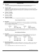
2841 E. Industrial Drive Springfield, MO 65802-6310 800-641-4282
XR5FC/XR5SL Installation Guide
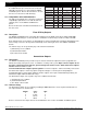
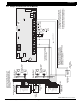
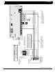
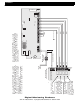
21.5 Supervised remote relay
ZONE 2
AC
1
234
78
10 11 12
13
14
15
16
AC B+ B–
9
RED
YEL GRN
BLK
Z1B–
Z2 –
Z2+
3.3k Ω
U21
1
2
3
4
J12
Z1A–
Z1B+
Z1A+
MODEL XR5
MAIN
BACKUP
PANEL
RESET
EPROM Socket
J11
N/C COM N/O N/C COM N/O
J4
J5
Telephone Connections
ZONE 1
S
S
5
6
BELL
SMK
OUTPUT 1
OUTPUT 2
SILENCE/RESET
PUSH FOR ONE SECOND
17
18
Z3 –
Z3+
19
20
Z4 –
Z4+
21
22
Z5 –
Z5+
W
W
3.3k Ω
ZONE 4
3.3k Ω
ZONE 3
1
2
3
4
5
6
7
8
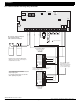
Auxiliary Power
Ground
Alarm Input
Bell Power Input
Bell Output +
Bell Output -
Bell Trouble
Bell Trouble
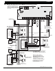
DMP part #DI-0001 Rectifier
(1N4001 diode) in series with
input from Model 866 terminal 6.
10k Ω EOL Resistor
DMP Model 308
Notification Circuit Module
DMP Model 866
37mA at 12 VDC
3.3k Ω
Normally Open
contacts will close
on alarm.
Normally Closed
contacts will open
on alarm.
DPDT Relay
Use Model ASRB-1 from Advanced Signaling
or Model RBSN-TTL from Altronix.
30mA coil operating current at 12 VDC.
Output 2 Normally Open
Remote DPDT
Relay
Supervised
Silence switch
Wiring between the 866 module and the
DPDT relay is supervised against opens,
shorts, and grounds. Either of these
trouble conditions cause the 866 module's
Bell Trouble contacts to open.
The zone connected to the Bell Trouble
contacts on the 866 Notification Circuit
Module must be programmed as a
Supervisory Type zone.
Output 1 Common
Modules must be installed in a
Model 340FC, 340SL, 349, or 350
enclosure connected by no more
than 20 feet of conduit.
S
= Supervised Circuit
S
SS S
S
S S S S S S
S S
S
S
S