
Installation guide

Page 16
Installation
2841 E. Industrial Drive Springfield, MO 65802-6310 800-641-4282
XR5FC/XR5SL Installation Guide
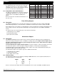
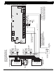
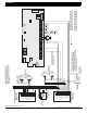
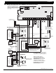
21.4 Remote Station reversing relay connection
ZONE 2
AC
1
234
78
10 11 12
13
14
15
16
AC B+ B–
9
RED
YEL GRN
BLK
Z1B–
Z2 –
Z2+
3.3k Ω
U21
1
2
3
4
J12
Z1A–
Z1B+
Z1A+
MODEL XR5
MAIN
BACKUP
PANEL
RESET
EPROM Socket
J11
N/C COM N/O N/C COM N/O
J4
J5
Telephone Connections
ZONE 1
S
S
5
6
BELL
SMK
OUTPUT 1
OUTPUT 2
SILENCE/RESET
PUSH FOR ONE SECOND
17
18
Z3 –
Z3+
19
20
Z4 –
Z4+
21
22
Z5 –
Z5+
W
W
3.3k Ω
ZONE 4
3.3k Ω
ZONE 3
EARTH GROUND
+ Signal Voltage In
Alternate Alarm
Combo Alarm
GROUND
GROUND
- Signal Voltage In
- To Remote Receiver
+ To Remote Receiver
Auxiliary Power Input
EARTH GROUND
+ Signal Voltage In
Alternate Alarm
Combo Alarm
GROUND
GROUND
- Signal Voltage In
- To Remote Receiver
+ To Remote Receiver
Auxiliary Power Input
To Telephone Line
To Telephone Line
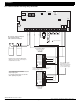
Reversing Relay Module
Radionics Model D127
12 VDC Supply
5mA Standby
55mA Alarm
Reversing Relay Module
Radionics Model D127
12 VDC Supply
5mA Standby
55mA Alarm
}
}
Up to 60 hours of battery standby time
can be supplied using two
7.0Ah sealed lead acid batteries.
Fire Trouble Output 2
Intended for connection to a polarity reversal
circuit of a Remote Station receiving unit
having compatible ratings.
Fire Alarm Output 1
Note: Output 1 must be
programmed as a Fire
Alarm Output and Output
2 must be programmed
as a Fire Trouble Output.
3.3k Ω
ZONE 5
Modules must be installed in a Model 340FC,
340SL, 349, or 350 enclosure connected by no
more than 20 feet of conduit.
This configuration transmits alarm and trouble
signals only and does not transmit
Supervisory signals.
For complete system reports, use the 2-line
dialer capability of the panel.
S
= Supervised Circuit
S
SS S
S S S S S S S S
SSSS