
Installation guide

Page 15
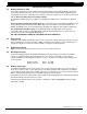
Installation
2841 E. Industrial Drive Springfield, MO 65802-6310 800-641-4282
XR5FC/XR5SL Installation Guide
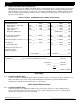
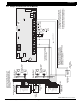
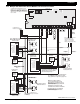
21.3 Multiple 866 Notification Circuit Modules for zoned annunciation
ZONE 2
AC
1
234
78
10 11 12
13
14
15
16
AC B+ B–
9
RED
YEL GRN
BLK
Z1B–
Z2 –
Z2+
3.3k Ω
U21
1
2
3
4
J12
Z1A–
Z1B+
Z1A+
MODEL XR5
MAIN
BACKUP
PANEL
RESET
EPROM Socket
J11
N/C COM N/O N/C COM N/O
J4
J5
Telephone Connections
ZONE 1
S
S
5
6
BELL
SMK
OUTPUT 1
OUTPUT 2
SILENCE/RESET
PUSH FOR ONE SECOND
17
18
Z3 –
Z3+
19
20
Z4 –
Z4+
21
22
Z5 –
Z5+
W
W
3.3k Ω
ZONE 4
ZONE 3
3.3k Ω
ZONE 5
1
2
3
4
5
6
7
8
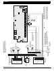
Auxiliary Power
Ground
Alarm Input
Bell Power Input
Bell Output +
Bell Output -
Bell Trouble
Bell Trouble
24 VDC 5 Amp
Maximum
Power Supply
Trouble Contacts
N/C
Zone 2 Notification Circuit
Module.
DMP Model 866
37mA at 12 VDC
The Auxiliary Power Supply and Notification
Circuit Module trouble contact zone must
be programmed as a Supervisory Type zone.
NOTE: If an auxiliary supply is
not used, terminals 3 and 4 on the
866 Notification Circuit Module can be
jumpered together to supply bell power
from the XR5F panel.
A maximum of 1.5 Amps at 12 VDC
is available from terminal 5 of the XR5FC.
Auxiliary power supplies must be
regulated UL listed for Fire Protection
Signaling Service. Power supplies
must have battery backup.
1
2
3
4
5
6
7
8
Auxiliary Power
Ground
Alarm Input
Bell Power Input
Bell Output +
Bell Output -
Bell Trouble
Bell Trouble
UL Listed, Polarized
Notification Devices.
10k Ω EOL Resistor
DMP Model 308
AUXILIARY
POWER
SUPPLY
AUXILIARY
POWER
SUPPLY
10k Ω EOL Resistor
DMP Model 308
1
2
3
4
5
6
7
8
Auxiliary Power
Ground
Alarm Input
Bell Power Input
Bell Output +
Bell Output -
Bell Trouble
Bell Trouble
UL Listed, Polarized
Notification Devices.
10k Ω EOL Resistor
DMP Model 308
AUXILIARY
POWER
SUPPLY
24 VDC 5 Amp
Maximum
24 VDC 5 Amp
Maximum
Zone 1 Notification Circuit
Module. DMP Model 866
37mA at 12 VDC
Common
Notification Circuit Module
DMP Model 866
37mA at 12 VDC
To additional Zone 1
Notification Circuit Modules.
To additional Zone 2
indicating circuit modules.
Zone 1
Output
Zone 2
Output
Each 866 Notification Circuit Module
in alarm draws up to 35mA from its
terminal 3 alarm input.
Output 1
Normally Open
Output 1 and 2
Common
Output 2
Normally Open
3.3k Ω
Note: The zone alarm action
programming must be
selected to activate relay
outputs 1 or 2 in order to
activate the appropriate relay.
To additional ten 866 Notification Circuit
Modules. Up to a maximum of thirteen 866
modules on the XR5FC panel. Modules must
be installed in a Model 340FC, 340SL, 349, or
350 enclosure connected by no more than 20
feet of conduit.
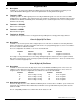
S
= Supervised Circuit
S
SS S S
S
S
S S
S S S
S
SS
S
S
S
S
S
S
S