
Installation guide

Page 12
Installation
2841 E. Industrial Drive Springfield, MO 65802-6310 800-641-4282
XR5FC/XR5SL Installation Guide
UNIVERSAL UL and NFPA FIRE ALARM SPECIFICATIONS
18.1 Introduction
The programming and installation specifications contained in this section must be completed when installing the
XR5FC and XR5SL panels in accordance with any of the UL or NFPA fire standards. Additional specifications
may be required by a particular standard.
18.2 Wiring
All wiring must be in accordance with NEC, ANSI/NFPA 70.
18.3 Police station phone number
The digital dialer telephone number programmed for communication must not be a police station phone number,
unless that phone number is specifically provided for that purpose.
18.4 System maintenance
Proper installation and regular maintenance by the installing alarm company and frequent testing by the end
user is essential to ensure continuous satisfactory operation of any alarm system. Offering a maintenance
program and acquainting the user with the correct procedure for use and testing of the system is also the
responsibility of the installing alarm company.
18.5 Audible alarm (XR5FC only)
Fire Type zones should be programmed to activate an audible alarm. The Bell Action for Fire Type zones should
not be programmed as “N”. See section 6.3A in the XR5FC and XR5SL Programming Guide (LT-0312).
18.6 UL Listed Receivers
UL has verified operation with the Sur-Gard SG-HLR2-DG, FBII CP220PB, Osborne-Hoffman Quick-Alert, and
Radionics D6500 receivers.
UL 864 NFPA 72 SPECIFICATIONS
Control Units for Fire Protective Signaling Systems
19.1 Power Fail delay
The Power Fail Delay option must be set to 6 hours. See section 5.4 of the Programming Guide (LT-0312).
19.2 Central Station Signaling Systems
Two phone lines must be used. The two phone lines cannot be ground start or party lines. See section 3.3 of the
XR5FC and XR5SL Programming Guide (LT-0312).
Two different phone numbers must be programmed for digital communication. See sections 3.12 and 3.15 of the
XR5FC and XR5SL Programming Guide (LT-0312).
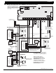
19.3 Local Protective Signaling Systems
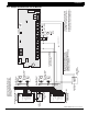
The DMP Model 865 or 866 Notification Circuit Module must be used on the bell circuit for detection of shorts
and grounds. See sections 20.1 to 20.3 of this guide.
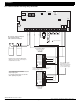
19.4 Remote Station Protective Signaling Systems
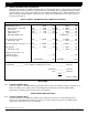
You must provide 60 hours of standby battery. Up to two 12 VDC, 7.0Ah batteries may be used. See section 6.6
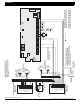
for standby battery calculations. Two Radionics Model D127 Reversing Relay Modules may be used to provide
two reversing polarity telephone connections instead of dual phone lines. See section 20.4 and the D127
Installation Instruction sheet for wiring details.
CALIFORNIA STATE FIRE MARSHAL SPECIFICATIONS
20.1 Bell output definition
The bell output of the Model XR5FC must be programmed to operate pulsed on fire alarms. See section 6.3A of
the XR5FC and XR5SL Programming Guide (LT-0312).