
Installation guide


Page 6
Installation
2841 E. Industrial Drive Springfield, MO 65802-6310 800-641-4282
XR5FC/XR5SL Installation Guide
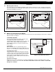
4.3 Mounting keypads
Security Command keypads have removable covers that allow you to easily mount the base to a wall or other
flat surface. After installing the keypad mounting anchors and bringing the keypad wiring from the panel through
the wall, mount the base and connect the keypad wire harness leads to the keypad wiring. Next, attach the
keypad wire harness connector to the pin connector on the keypad circuit board and install the cover.
For mounting keypads on masonry walls, or for applications where conduit is required, use an appropriate DMP
keypad conduit backbox.
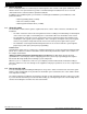
4.4 Wiring keypads
Keypad data bus
The keypad data bus consists of a 4-wire cable that provides
12 VDC power, data in, data out, and a panel common. You can
connect keypads in parallel on one 4-wire cable or provide a
separate cable run back to the panel for each keypad. The
maximum cable length for one keypad can be up to 500 feet
using 22 gauge wire or up to 1000 feet using 18 gauge wire.
Refer to the wiring diagram in this guide for additional wiring
information. See section 3.2.
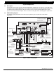
Primary Power Supply
5.1 Terminals 1 and 2
AC transformer input
Connect the wires from the Model 320, 16.5 VAC 40VA transformer to terminals 1 and 2 on the panel. Use no
more than 70 ft. of 16 gauge or 40 ft. of 18 gauge wire between the transformer and the XR5FC or XR5SL panel.
The transformer provides up to 500mA of auxiliary current for the XR5FC and XR5SL panels. The total current
available is limited by the total battery standby requirements of the installation. See section 6.6 for standby
battery calculations.
The transformer requires an unswitched 120 VAC 60 Hz electrical outlet with at least 350mA of available current.
Never share the transformer output with any other equipment. The 120 VAC circuit is not power limited.
DC power input to AC input
When powering the XR5FC/SL panel from the 12 VDC output of a FACP, connect the positive wire to the
positive battery terminal of the XR5 and the negative wire to the negative battery terminal of the XR5.
When powering the panel from the DC output of a 24 Volt Fire Alarm Control Panel (FACP), connect the
positive wire from the FACP to terminal 1 and the negative wire to terminal 2.
Do not use battery backup with 12 or 24 VDC input:
Do not connect
any
batteries to the XR5FC or XR5SL
panels when using the 12 or 24 VDC output from a FACP. The XR5FC and XR5SL panels use the backup
battery capability of the FACP for their standby requirements.
Features disabled when using 24 VDC power input:
When powering the XR5FC or XR5SL panel from the 24
VDC output of a FACP, the following operational features are disabled:
• Bell Output on the XR5FC
• AC test (XR5FC and XR5SL)
• Battery test (XR5FC and XR5SL)
Always ground the panel before applying power to any devices:
The XR5FC and XR5SL panels must be
properly grounded before connecting any devices or applying power to the panels. Proper grounding protects
against Electrostatic Discharge (ESD) that can damage system components. See Earth ground, section 6.2.
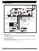
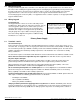
Figure 5: Proper wiring connections
In all applications where more than
one wire is under a terminal, the
wire must be cut and not looped
around the screw terminal.